Mele M5
| Mele M5 | |
|---|---|
 | |
| Manufacturer | Mele |
| Dimensions | 175mm x 110mm x 47mm |
| Release Date | August 2013 |
| Website | Product Catalog |
| Specifications | |
| SoC | A20 @ 1 GHz |
| DRAM | 1GiB DDR3 @ 384 MHz |
| NAND | 8 GB |
| Power | DC 5V @ 2A |
| Features | |
| Video | HDMI (Type A - full), Composite |
| Audio | R/L Cinch, HDMI, SPDIF |
| Network | WiFi 802.11 b/g/n (Realtek RTL8188EUS), 10/100Mbps Ethernet (Realtek RTL8201CP) |
| Storage | SD, SATA |
| USB | 3 USB 2.0 Host |
| Headers | UART |
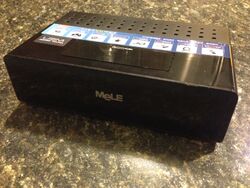
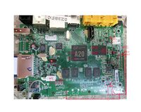
The Mele M5 is an A20 based upgrade to the Mele A1000 family of set-top-boxes. The Mele M5 shares the same case as the Mele A1000, but uses the same motherboard as the A3700, however with an A20 SoC.
Identification
The manufacturer name and model-number are clearly printed on a label on the bottom of the device.
Sunxi support
Current status
Supported.
Images
HW-Pack
BSP
Manual build
- For building u-boot, use the "Mele_M5" target.
- The .fex file can be found in sunxi-boards as mele_m5.fex
Everything else is the same as the manual build howto.
Tips, Tricks, Caveats
FEL mode
The Mele A1000 can be put into FEL mode by shorting jumper 11K1. This has not been verified to work on the M5.
Adding a serial port
Device disassembly
Trivially unscrew 4 screws.
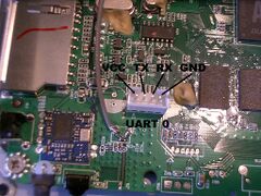
Locating the UART
The Mele has a 4 pin 2.0 pitch JST-PH connector available for its UART0 port. This is the same as some 90s analog audio cables which ran from a CDROM to the sound card. More information is available at our UART howto.
Pictures
Also known as
Like the Mele A1000 family, the Mele M5 appears to have two A20 based siblings: the Mele M3 and Mele M6.
GPIO
There are approximately 30 GPIO pins available on the top side
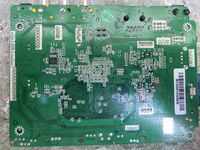
and at least 4 GPIO pins accessible on the bottom face of the board.
To access to all of them you need to disable some features of the motherboard in the script.bin file. For example to access the pins used for flash memory that is present on the motherboard you must before desolder the flash memory and change the file script.bin properly.
The following file File: File:Script.fex.30gpios.pdf offers access to at least 31 GPIO pins.
See also
- Mele A1000: The original A10 based Mele
- Mele A1000G Quad: A quad-core A31 based Mele


