MangoPi
MQ-R
| MangoPi MQ-R | |
|---|---|
 | |
| Manufacturer | MangoPi |
| Dimensions | 30mm x 45mm |
| Release Date | ? |
| Website | Product Page |
| Specifications | |
| SoC | D1s @ 1.0Ghz / T113-s3 @ 1.0Ghz |
| DRAM | 64MiB (D1) @ / 128 MiB (T113-s3) |
| Power | DC 5V @ 2A (via OTG or dedicated USB Type-C connector) |
| Features | |
| Video | RGB-LCD FPC connector |
| Audio | built in microphone |
| Network | WiFi 802.11 b/g/n RTL8189F or RTL8723ds WiFi/BT |
| Storage | µSD, SPI NAND (unsoldered) |
| USB | 1 USB2.0 Type-C Host, 1 USB Type-C OTG |
| Other | BOOT & FEL buttons |
| Headers | 2x18-pin extension header, 15-pin MIPI DSI, 40-pin FPC LCD RGB 24Pins DVP FPC connector 6Pins CTP FPC connector, antenna connector |
A small development board, available in both a RISC-V version and an ARM version.
Identification
The PCB has the following silkscreened on it:
MangoPi MQ-R
The RISC-V version can be identified by the label on the SoC reading "F133-A" (a relabeled D1s), the ARM version reads "T113-S3" on the SoC.
Sunxi support
Current status
The ARM version is supported in mainline Linux and U-Boot, the RISC-V version should work in the kernel, given the right devicetree, which is not mainlined. U-Boot support for the D1(s) is still missing in general.
Manual build
You can build things for yourself by following our Manual build howto and by choosing from the configurations available below.
Mainline U-Boot
Use the mangopi_mq_r_defconfig build target. Available since v2024.01-rc1.
Mainline Linux Kernel
Use the sun8i-t113s-mangopi-mq-r-t113.dtb devicetree binary from a mainline kernel, available since v6.5-rc1.
Wifi
There is no Wifi driver for the chip in mainline, see Wifi#RTL8189ES_.2F_RTL8189ETV
Tips, Tricks, Caveats
FEL mode
The board has a FEL button on the underside of the PCB, near the board's edge. The button closer to the SD card slot is the reset button.
The USB type-C socket labelled "OTG" (next to the antenna connector) is connected to USB controller 0, a standard USB-A - USB-C cable can be used for FEL booting.
Serial port
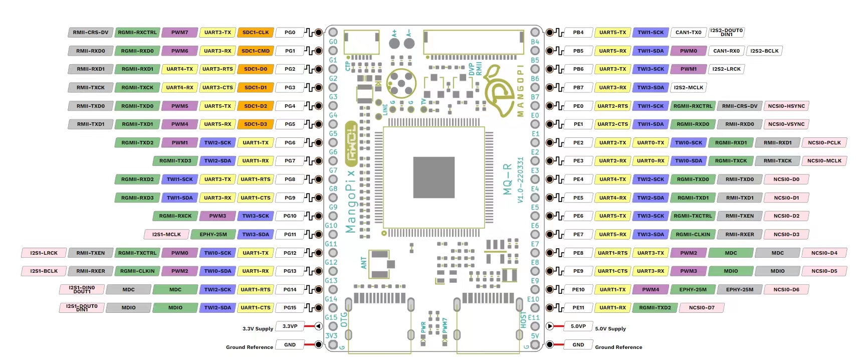
The board has no dedicated UART connector, but has two prominent UART pins on the (unsoldered) in-line header connector. UART0 is available on pins PE2/PE3, the UART3 RX/TX pins are on pins PB6/PB7. While UART0 is the more natural debug console port, the schematic clearly designates UART3 as the debug UART, so the DT and U-Boot's defconfig select this UART and its PB pins for this purpose.
Please note that the pin names are written below the pins, so the top-most pin is PB4, and UART3 RX/TX are on the third and fourth pin.