MangoPi MQ-Pro
| MangoPi MQ-Pro | |
|---|---|
 | |
| Manufacturer | MangoPi |
| Dimensions | 65mm x 30mm |
| Release Date | April 2022 |
| Website | Home Page |
| Specifications | |
| SoC | D1 @ 1.0Ghz |
| DRAM | 512MiB DDR3 @ 792MHz, 1×H5TQ4G63EFR or 1GiB DDR3(L) |
| Power | DC 5V @ 2A (via OTG Type-C connector) |
| Features | |
| Video | HDMI (Type C - Mini) |
| Audio | HDMI, I2S |
| Network | Trolink TL8723DS Wi-Fi+BT, Ethernet via optional secondary board |
| Storage | µSD, optional SPI flash (bottom) |
| USB | 1 USB Type-C OTG, 1 USB Type-C USB host |
| Other | RMII/RGMII flex connector |
This page needs to be properly filled according to the New Device Howto and the New Device Page guide.
Hardware comaptibility
MangoPi MQ-Pro is a D1 based board in the Pi Zero form factor, so it fits in cases made for the Pi Zero.
It is even pin compatible, allowing for using various gadgets made for Pi Zero boards with it, e.g., GamePi15. See the pictures for examples.
Identification
Visually, two PCB colors exist, pink and red. The front side has a D1 chip and "MangoPi MQ-Pro" written on the PCB. The back side contains the MangoPi logo, MangoPi.CC website as well as "Card computer" followed by the PCB revision.
Versions
Two versions exist:
- MPi-MQ1PL: 512MiB RAM
- MPi-MQ1PH: 1GiB RAM. Due to supply chain issues, second hand 1GiB DDR3/DDR3L chips are being used of various models. Some examples are MT41K512M16HA-125 and EDJ8416E6MB-GN-F.
At the bottom are solder pads for a SPI flash, NAND or NOR. A white dot in the top left marks pin 1 (CS).
PCB revisions
There are several PCB revisions, indicated on the back side of the board.
| Revision | Date | PCB color | Details |
|---|---|---|---|
| v1.0 | 2022.01.05 | Green | first release mini-HDMI error |
| v1.1 | 2022.01.17 | Green | HDMI fix |
| v1.2 | 2022.02.04 | Red | small batch |
| v1.3 | 2022.04.15 | Pink | small batch new FEL/RST pad location |
| v1.4 | 2022.06.27 | Pink | mass production vias filled with resin antenna trace optimization |
Software Support
Linux and U-Boot upstreaming are in progress. See Allwinner_Nezha#Manual_build for build instructions. For U-Boot, use the mangopi_mq_pro_defconfig configuration.
Distro support
- Working community Armbian build available here: Armbian_22.08.0-trunk_Nezha_jammy_current_5.19.0_xfce_desktop.img
- Armbian buildup thread here
- ArchLinux, as made with Sehraf Arch Image Builder (linux mainline with Sameul patch) works just fine. This build add ArchLinux rootFS on the SDcard, but any linux distribution for RISC-V 64 bits should just works fine.
- Postmarket OS,See Postmarket Os Wiki for more info
Pictures
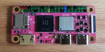
front view
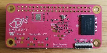
back view
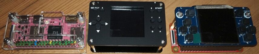
MangoPi Pro fits in many cases made for the Raspberry Pi Zero


GPIO bus pin colors
Description can be found on the 3rd page of Board schematics (See below in #External links section).
- Black are Ground
- Red are 5V
- Yellow are 3.3V
- Blue are 27 (SDA (data)/PE17 and 28 (SCL (clock)/PE16), TWI3.
Serial pins are:
- TX0/RX0 pins 8/10
- TX1/RX1 pins 11/13
- TX2/RX2 pins 32/22
See GPIO page for using them with Linux kernel.
FEL mode and reset
Note that there are no buttons on the board. However, there are labeled test points at the back for both FEL and reset with a ground test point next to them, so that you can attach wires and add your own buttons somehow, maybe combined with a case.
Apparently, FEL mode can be also accessed by plugging in the board without SD Card.
Commands sent through sunxi-fel will not work and will cause a USB timeout.
To init DRAM, run:
xfel ddr d1
# OpenSBI fw_jump.bin
xfel write 0x40000000 fw_jump.bin
xfel exec 0x40000000