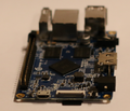
Xunlong Orange Pi PC
| Xunlong Orange Pi PC | |
|---|---|
 | |
| Manufacturer | OrangePi |
| Dimensions | 85mm x 55mm |
| Release Date | August 2015 |
| Website | Orange Pi PC Product Page |
| Specifications | |
| SoC | H3 @ 1.3 GHz |
| DRAM | 1GiB DDR3L (v1.2 K4B4G1646Q-HYK0, v1.3 K4B4G1646E-BYK0) |
| Power | DC 5V @ 2A (4.0mm/1.7mm barrel plug - centre positive) or via GPIO header pins |
| Features | |
| Video | HDMI (HDCP, CEC), CVBS |
| Audio | 3.5 mm Jack, HDMI, Microphone |
| Network | 10/100 Ethernet |
| Storage | µSD, 8GB eMMC on PC Plus |
| USB | 3 USB 2.0 Host, 1 USB 2.0 OTG |
| Other | CIR |
| Headers | 3 pin UART, CSI, 40 pin GPIO |
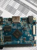
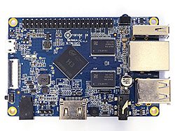
Orange Pi PC is H3 based development board produced by Xunlong.
Identification
The PC PCB has the following silkscreened on it:
Orange Pi PC V1.2
Since 2016 (maybe earlier?), an updated version with a bit thinner memory chips (see the spec sheets for differences between the memory types) is available with the following silkscreened on it:
Orange Pi PC V1.3
The PC Plus PCB shows the following:
Orange Pi PC Plus V1.1
Sunxi support
Current status
The H3 SoC support has matured since its introduction in kernel 4.2. Most of the board functionality for boards such as Orange Pi PC are available with current mainline kernels. Some features (hw accelerated crypto, hw spinlocks, and thermal) are still being worked on. For a more comprehensive list of supported features, see the status matrix for mainline kernels. In addition, legacy 3.4 kernels are available in various work-in-progress git branches.
See the Manual build section for more details.
Manual build
You can build things for yourself by following our Manual build howto and by choosing from the configurations available below.
U-Boot
Mainline U-Boot
Use the orangepi_pc_defconfig (supported since v2016.01) build target. The U-Boot repository and toolchain is described in the Mainline U-Boot howto.
The H3 boards can boot from SD cards, eMMC, NAND or SPI NOR flash (if available), and via FEL using the OTG USB port. In U-Boot, loading the kernel is also supported from USB or ethernet (netboot). HDMI support in U-Boot is still WIP.
Linux Kernel
Sunxi/Legacy Kernel
The 3.4 kernel from the official Allwinner's git repository does not support H3 yet. But it is possible to use one of the kernel forks, based on the lichee H3 SDK tarball:
- Siarhei Siamashka's branch '20151207-embedded-lima-memtester-h3'
- Yann Dirson's fork added a few more fixes and adopted most of
- Boris Lovosevic' great initial work on Allwinner's H3 kernel
Configure this kernel using sun8i_h3_defconfig, the rest is explained in the kernel compilation guide.
Use the .fex file for generating script.bin. The .fex file is available from xunlong_orange_pi_pc.fex.
When booting the legacy 3.4 kernel with the mainline U-Boot, add the following line to boot.cmd:
  setenv machid 1029
  setenv bootm_boot_mode sec
Some other legacy kernel repositories:
- 3.4-lichee-based kernel, based on work by ssvb and loboris
- Yocto support here glues together all the required parts to get this kernel to work with mainline u-boot, as well as accelerated X11/GLES support
- A newer H3 BSP variant appeared with tons of fixes which has been made available by FriendlyARM.
- A cleaned up fork has been adopted by Armbian project. On top of that Armbian maintains a bunch of 3.4.x patches for H3 devices.
Mainline kernel
The mainline kernel has good support for the H3 SoC. Please refer to the status matrix for a more detailed list of the development process, links to patches and links to kernel fork repositories. Minor drivers that are currently work-in-progress may require a) third party patches (see also arm-linux mailing list) or b) a pre-patched distro (e.g. Armbian).
Repositories with H3 patches:
- Ondřej Jirman's branch for H3 based orange Pi (kernel 4.19) (work-in-progress DVFS)
- Thermal regulation (if CPU heats above certain temperature, it will try to cool itself down by reducing CPU frequency)
- HDMI audio support (from Jernej Skrabec)
- Configure on-board micro-switches to perform system power off function
- Wireguard (https://www.wireguard.com/)
- Philipp Rossak's THS patches (in the sunxi-ths- branches)
- Corentin Labbe's HW Crypto and spinlock patches (in respective branches)
Use the sun8i-h3-orangepi-pc.dtb device-tree binary.
Expansion Port
The Orange Pi PC has a Raspberry Pi model B+ compatible 40-pin, 0.1" connector with several low-speed interfaces.
| 2x20 Header | |||
|---|---|---|---|
| 1 | 3.3V | 2 | 5V |
| 3 | PA12 (TWI0_SDA/DI_RX/PA_EINT12) | 4 | 5V |
| 5 | PA11 (TWI0_SCK/DI_TX/PA_EINT11) | 6 | GND |
| 7 | PA6 (SIM_PWREN/PWM1/PA_EINT6) | 8 | PA13 (SPI1_CS/UART3_TX/PA_EINT13) |
| 9 | GND | 10 | PA14 (SPI1_CLK/UART3_RX/PA_EINT14) |
| 11 | PA1 (UART2_RX/JTAG_CK/PA_EINT1) | 12 | PD14 |
| 13 | PA0 (UART2_TX/JTAG_MS/PA_EINT0) | 14 | GND |
| 15 | PA3 (UART2_CTS/JTAG_DI/PA_EINT3) | 16 | PC4 |
| 17 | 3.3V | 18 | PC7 |
| 19 | PC0 (SPI0_MOSI) | 20 | GND |
| 21 | PC1 (SPI0_MISO) | 22 | PA2 (UART2_RTS/JTAG_DO/PA_EINT2) |
| 23 | PC2 (SPI0_CLK) | 24 | PC3 (SPI0_CS) |
| 25 | GND | 26 | PA21 (PCM0_DIN/SIM_VPPPP/PA_EINT21) |
| 27 | PA19 (PCM0_CLK/TWI1_SDA/PA_EINT19) | 28 | PA18 (PCM0_SYNC/TWI1_SCK/PA_EINT18) |
| 29 | PA7 (SIM_CLK/PA_EINT7) | 30 | GND |
| 31 | PA8 (SIM_DATA/PA_EINT8) | 32 | PG8 (UART1_RTS/PG_EINT8) |
| 33 | PA9 (SIM_RST/PA_EINT9) | 34 | GND |
| 35 | PA10 (SIM_DET/PA_EINT10) | 36 | PG9 (UART1_CTS/PG_EINT9) |
| 37 | PA20 (PCM0_DOUT/SIM_VPPEN/PA_EINT20) | 38 | PG6 (UART1_TX/PG_EINT6) |
| 39 | GND | 40 | PG7 (UART1_RX/PG_EINT7) |
Tips, Tricks, Caveats
- Heat issues when using common OS images for the OPi PC. Without a heatsink the Orange Pi PC overheats easily and will drop cores to thwart further temperature increase and unfortunately the heatsink provided by the manufacturer does little to help. The low cost $15 variant does not have any heatsink included at all. This is the result of 'factory settings' overclocking/overvolting the H3 way too much. With adjusted dvfs entries and an upper limit of 1.2 GHz SoC temperature stays below 75°C without heatsink when running cpuburn-a7 on all 4 cores. Using a quality heatsink, some airflow and reasonable cpufreq settings the H3 remains below 60°C even under full load at an ambient temperature of 22°C.
- It is also possible to power the device via GPIO pin header: connect +5V to either pin 2 or 4 (both are connected to DCIN test point) and GND to pin 6.
FEL mode
There is no dedicated FEL button. The Orange Pi PC will fail over to FEL mode if it doesn't detect a card present in the µSD slot. On the PC Plus it gets somewhat tricky to use FEL mode in case the eMMC is already populated with an OS (or at least a working boot loader). In this case it helps to grab the fel-sdboot.sunxi image from sunxi-tools github repo and write it to an SD card of any size as follows:
sudo dd if=fel-sdboot.sunxi of=/dev/sdX bs=1024 seek=8
Then boot afterwards with this SD card inserted and H3 will be in FEL mode afterwards.
An alternative way is to power the board from Pin2 (5V GPIO)whilst connected to RX/TX with a USB Serial TTL Spam '2' over the serial console. This will place the board into FEL mode - no SD-Card image required. Tested and works on Pi PC Plus.
Not tested yet
You can use "FAKE FEL BUTTON". See photo "H3_FAKE_BUTTON". According to the board's schematic UBOOT pin is connected to R124 (bottom leed, because top leed is connected to R38 which is connected to VCC). You can connect it to GND. The right R108 leed is the nearest GND pin (I've checked it). It is very close so it is not too hard. I draw it as yellow line. Enjoy!
LEDs
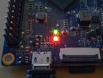
The board has two LEDs:
- A red LED, connected to the PA15 pin.
- A green LED, connected to the PL10 pin.
When using kernel 3.4 with Xunlong's or loboris' settings then the LEDs can only be switched on/off. By changing the definition in the fex file (see patch or fex with applied fix) both LEDs can be used the usual way (using different triggers and so on)
CPU clock speed limit
The Allwinner H3 manual does not provide the CPU clock speed information. But the following is a common comment in the FEX files from various H3 SDK variants:
; dvfs voltage-frequency table configuration
;
; pmuic_type:0:none, 1:gpio, 2:i2c
; pmu_gpio0: gpio config.
; pmu_levelx: 0~9999: voltage(mV), 10000~90000:gpio0 state. voltage form high to low.
;
; extremity_freq(Hz): cpu extremity frequency when run benckmark or demo apk
;                     1536MHz@1500mV with radiator, 1296MHz@1340mV without radiator
; max_freq: cpu maximum frequency, based on Hz, can not be more than 1200MHz
; min_freq: cpu minimum frequency, based on Hz, can not be less than 60MHz
;
; LV_count: count of LV_freq/LV_volt, must be < 16
;
; LV1: core vdd is 1.50v if cpu frequency is (1296Mhz,  1536Mhz]
; LV2: core vdd is 1.34v if cpu frequency is (1200Mhz,  1296Mhz]
; LV3: core vdd is 1.32v if cpu frequency is (1008Mhz,  1200Mhz]
; LV4: core vdd is 1.20v if cpu frequency is (816Mhz,   1008Mhz]
; LV5: core vdd is 1.10v if cpu frequency is (648Mhz,    816Mhz]
; LV6: core vdd is 1.04v if cpu frequency is (0Mhz,      648Mhz]
; LV7: core vdd is 1.04v if cpu frequency is (0Mhz,      648Mhz]
; LV8: core vdd is 1.04v if cpu frequency is (0Mhz,      648Mhz]
It means that this comment likely originates from Allwinner, rather than something added by Xunlong or any other H3 device manufacturer.
The Orange Pi PC board uses the SY8106A voltage regulator for providing the CPU core voltage (VDD_CPUX). The default CPU voltage is 1.2V after power-on (selected by the resistors on the PCB) and can be changed at runtime by software via I2C interface. According to the table above, this default voltage should be safe for using with the CPU clock frequencies up to 1008MHz. The H3 datasheet specifies 1.5V as the absolute maximum for the VDD_CPUX voltage and 1.4V as the recommended maximum.
DRAM clock speed limit
DRAM is clocked at 672 MHz by the hardware vendor. But the reliability still needs to be verified. One of the ways of doing reliability tests may be https://github.com/ssvb/lima-memtester/releases/tag/20151207-orange-pi-pc-fel-test (it checks the Orange Pi PC DRAM setup in the current mainline U-Boot v2016.01-rc2 + a bugfix).
| Hardware | Diagnostic software | lima-memtester passes (survives until the red LED) | lima-memtester fails | Notes |
|---|---|---|---|---|
| User:Ssvb's Orange Pi PC | fel-boot-lima-memtester-on-orange-pi-pc-v3.tar.gz | 672 MHz | 696 MHz | No heatsink. 696 MHz fails after running for just a few seconds, so not much confidence in 672 MHz either |
| User:Tkaiser's 1st Orange Pi PC | fel-boot-lima-memtester-on-orange-pi-pc-v3.tar.gz | 672 MHz | 696 MHz | Small heatsink. 696 MHz fails after running for 2-3 minutes |
| Orange Pi PC v1.2 (plaes) | fel-boot-lima-memtester-on-orange-pi-pc-v3.tar.gz | 648 MHz | 672 MHz | No heatsink. Multiple reproducible failures. SoC markings: F7004BA 68D3, Memory: Samsung K4B4G1646Q-HYK0 |
| User:Tkaiser's 2nd Orange Pi PC | fel-boot-lima-memtester-on-orange-pi-pc-v3.tar.gz | 672 MHz | 696 MHz | No heatsink. 696 MHz fails after running for ~10 minutes |
| User:Peko's Orange Pi PC | fel-boot-lima-memtester-on-orange-pi-pc-v3.tar.gz | 720 MHz | 744 MHz | Heatsink. 744 MHz fails after running for ~1-2 minutes |
| User:Patapovich's Orange Pi PC | fel-boot-lima-memtester-on-orange-pi-pc-v3.tar.gz | 672 MHz | 696 MHz | No heatsink. 672 MHz was running for ~16 hours without problems |
| User:Runnerway's Orange Pi PC | fel-boot-lima-memtester-on-orange-pi-pc-v3.tar.gz | 672 MHz | 696 MHz | Small heatsink. |
| User:Camh's Orange Pi PC 1 | fel-boot-lima-memtester-on-orange-pi-pc-v3.tar.gz | 744 MHz | 768 MHz | Heatsink (35mmx25mm) covering SoC and RAM. 768MHz failed < 1 min. |
| User:Camh's Orange Pi PC 2 | fel-boot-lima-memtester-on-orange-pi-pc-v3.tar.gz | 696 MHz | 720 MHz | Heatsink (35mmx25mm) covering SoC and RAM. 720MHz failed after 5 mins. |
| User:Camh's Orange Pi PC 3 | fel-boot-lima-memtester-on-orange-pi-pc-v3.tar.gz | 696 MHz | 720 MHz | Heatsink (35mmx25mm) covering SoC and RAM. 720MHz failed after ~30 mins. |
| User:Camh's Orange Pi PC 4 | fel-boot-lima-memtester-on-orange-pi-pc-v3.tar.gz | 672 MHz | 696 MHz | Heatsink (35mmx25mm) covering SoC and RAM. 696MHz failed in < 30s. |
| lymon's Orange Pi PC | fel-boot-lima-memtester-on-orange-pi-pc-v3.tar.gz | 672 MHz | 696 MHz | fails/hangs after approx. 10 minutes |
| User:Michal's Orange Pi PC | fel-boot-lima-memtester-on-orange-pi-pc-v3.tar.gz | 696 MHz | 720 MHz | No heatsink. At 720 MHz test failed in about 5 minutes. |
| User:Jvdwaa's Orange Pi PC | fel-boot-lima-memtester-on-orange-pi-pc-v3.tar.gz | 720 MHz | 744 MHz | No heatsink. |
| User:dusthillguy's Orange Pi PC | fel-boot-lima-memtester-on-orange-pi-pc-v3.tar.gz | 672 MHz | 696 MHz | Only one 14mm*14mm*5mm heatsink, fitted on the H3 chip. Stable at 672 for over 12 hours without a fan, the green led was still flashing when I powered the system off. Fails within 30 to 60 minutes at 696 without a fan. At 696 with a fan, it survives for a few hours, but even with the fan it does eventually fail (the LEDs go off).
By the way, the fan I used is 70mm, taken from an old intel heatsink, and powered by USB, so it rotates at a low speed. Just in case this is useful to know. |
| kc's Orange Pi PC | fel-boot-lima-memtester-on-orange-pi-pc-v3.tar.gz | 648 MHz | 672 MHz | No heatsink. stable for ~35minutes of testing at 648 (to the red led), failing within 1-2 minutes at 672.
board label: 112169, SOC markings: F7008BA 68E3, ram markings: K4B4G1646Q-HYKO / EKG384K8C |
| User:fjen's Orange Pi PC | fel-boot-lima-memtester-on-orange-pi-pc-v3.tar.gz | 720 MHz | 744 MHz | 14mm*14mm*8mm Heatsink on H3. 744 MHz fails after 1 minute |
| User:dvl36's Orange Pi PC | fel-boot-lima-memtester-on-orange-pi-pc-v3.tar.gz | 720 MHz | 744 MHz | Heatsink (35x35x25mm) covering SoC and RAM. 744 MHz fails after ~2 minutes. |
| User:cosm's Orange Pi PC | fel-boot-lima-memtester-on-orange-pi-pc-v3.tar.gz | 648 MHz | 672 MHz | 22mm*22mm*10mm heatsink on the SoC only. 672 MHz worked until the red LED lit, but failed after about two hours. 648 MHz was still working after 10 hours. |
| User:hp197's Orange Pi PC | fel-boot-lima-memtester-on-orange-pi-pc-v3.tar.gz | 696 MHz | 720 MHz | Heatsink (13x14x6.5mm) covering only SoC (Ebay Link). 720Mhz Failed quick after start (at the bit flip test, 1st pass). |
| User:emsi88's Orange Pi PC | fel-boot-lima-memtester-on-orange-pi-pc-v3.tar.gz | 672 MHz | 696 MHz | With big heatsink . 696 Mhz Failed afrer few minutes, 672 MHz worked stable for over 9 hours. |
| User:lampra's Orange Pi PC | fel-boot-lima-memtester-on-orange-pi-pc-v3.tar.gz | 648 MHz | 672 MHz | No heatsink. 672 Mhz Failed afrer few minutes. |
| User:Tkaiser's Orange Pi PC Plus | fel-boot-lima-memtester-on-orange-pi-pc-v3.tar.gz | 672 MHz | 696 MHz | Cheap heatsink. 696 MHz fails after running for 90 seconds |
| User:Euros's Orange Pi PC Plus | fel-boot-lima-memtester-on-orange-pi-pc-v3.tar.gz | 648 MHz | 672 MHz | No heatsink. 672 MHz failed after 50 minutes, 648 MHz was still working after 20 hours. |
We need still more test results in the table above in order to have more accurate statistics and finally pick a safe default DRAM clock speed for U-Boot. Preferably there should be at least 10 entries in the table (more is always better). And there are no "good" or "bad" test results. Even if your result looks very similar to the already reported results from the other people, please still add yours to the table! Because if people don't feel like reporting their "boring" results, then "interesting" outliers will unfortunately skew the statistics. Thanks!
DRAM clock speed limit (automated statistical analysis)
Below is an intermediate analysis of the currently reported results, using the lima-memtester-genchart script (run the script using this page URL as the command line argument). Assuming that the Gaussian distribution is a good approximation, try to predict what percentage of boards is expected to pass the lima-memetser test at different DRAM clock frequencies. The lima-memtester page provides more information.
Updating the analysis report:
wget https://raw.githubusercontent.com/ssvb/lima-memtester/master/lima-memtester-genchart
ruby lima-memtester-genchart https://linux-sunxi.org/Xunlong_Orange_Pi_PC
# copy/paste the script output into the linux-sunxi wiki
| DRAM clock speed | Percentage of boards failing the lima-memtester test | Theoretical pessimistic upper bound of the failure percentage using Chebyshev's inequality for lower semivariance [1] | Histogram | |
|---|---|---|---|---|
| Experimental results | Theoretical prediction (assuming Gaussian distribution) [2] | |||
| 528 MHz | 0.00 % (0/24) | 0.00 % | 1.07 % | |
| 552 MHz | 0.00 % (0/24) | 0.00 % | 1.46 % | |
| 576 MHz | 0.00 % (0/24) | 0.00 % | 2.12 % | |
| 600 MHz | 0.00 % (0/24) | 0.03 % | 3.34 % | |
| 624 MHz | 0.00 % (0/24) | 0.52 % | 6.02 % | |
| 648 MHz | 0.00 % (0/24) | 4.62 % | 13.93 % | |
| 672 MHz | 20.83 % (5/24) | 21.04 % | 60.91 % | ***** |
| 696 MHz | 62.50 % (15/24) | 52.92 % | 100.00 % | ********** |
| 720 MHz | 79.17 % (19/24) | 82.93 % | 100.00 % | **** |
| 744 MHz | 95.83 % (23/24) | 96.63 % | 100.00 % | **** |
| 768 MHz | 100.00 % (24/24) | 99.66 % | 100.00 % | * |
- ↑ If nothing is known about the distribution of samples, then at least Chebyshev's inequality can be used to get a rough idea about the probabilities of encountering reliability problems at different DRAM clock speeds. But this method is very conservative and substantially overestimates probabilities (being too generic has its price).
- ↑
We can assume that the Gaussian distribution
is a good approximation for our experimental data, calculate theoretical probabilities and do an
exact test of goodness-of-fit
to see if the experimental data does not contradict with the theory.
There is a nice XNomial
library for R, which can do the job:
    P value  (LLR)  =  0.5844
    P value (Prob)  =  0.6122
    P value (Chisq) =  0.6687
If the p-values listed above happen to be too low (less than 0.05) and reject our null hypothesis about having the Gaussian distribution, then Chebyshev's inequality estimates still can be used.
OpenRISC core
Also named as AR100, CPUS and "arisc" in various Allwinner materials, which may cause a bit of confusion. According to the Orange Pi PC schematics, VDD_CPUS is connected to VDD_RTC. It means that the voltage powering the OpenRISC core is programmable via the hardware register VDD_RTC_REG (at 0x1F00190) and can be configured between 0.7V and 1.4V. The H3 datasheet says that 1.4V is the absolute maximum for VDD_CPUS and 1.1V-1.3V is the recommended range. The reset default for VDD_RTC voltage is 1.1V.
Below is a quick evaluation of the potential clock speed limit of the OpenRISC core on just a single board (ssvb's) by running a naive recursive fibonacci function:
| VDD_RTC voltage | OpenRISC core deadlocks at | OpenRISC core does not obviously fail at | OpenRISC core is reliable at | ||
|---|---|---|---|---|---|
| Without I-Cache | With I-Cache | Without I-Cache | With I-Cache | ||
| 1.1V | 552 MHz | 456 MHz | 528 MHz | 432 MHz | ? |
| 1.2V | 624 MHz | 504 MHz | 600 MHz | 480 MHz | ? |
| 1.3V | 624 MHz | 504 MHz | 600 MHz | 480 MHz | ? |
Without I-Cache, fetching each instruction from SRAM takes 3 cycles instead of just 1.
Please note that the intended use of the OpenRISC core in Allwinner devices is keeping a watch while the main Cortex-A7 CPU and the rest of the SoC peripherals are powered off in deep power save modes. In this usage scenario it is likely clocked at just the minimum possible clock frequency 32 KHz.
USB
It should be noted that unlike some of the more expensive Orange Pi models the 'PC' does not use an internal USB hub therefore the 4 available USB ports don't have to share bandwidth. First tests with kernel 4.4.0-rc4, a fast SSD and an enclosure capable of USB Attached SCSI show excellent sequential performance with mainline kernel: 39 MB/s write and 41.5 MB/s read (tests done with iozone using 4 GB test size and averaging the values of 4K/1M record size)
Camera module
Xunlong sells also a cheap 2MP camera (an attempt to fix the driver's limited resolutions can be found here). Unlike Orange Pi Plus/2 that can directly connect to the camera module for the PC an 'expansion board' is needed (see gallery below). If you order from Xunlong simply say that you need the camera for Orange Pi PC and they ship camera together with the small board.
1-Wire support
After applying a [1] to the lichee kernel sources 1-wire can be used with H3 based Orange Pi's. After loading the approriate modules (w1-sunxi, w1-gpio and w1-therm) connected 1-wire slave devices should appear below /sys/bus/w1/devices/. To let 1-wire work the GPIO pin to be used has to be defined in fex/script.bin. All OS images that applied the 1-wire patch (all from loboris after applying his latest fixes, Armbian or the community's OpenELEC build) use "gpio = 20" in the fex file. Attention: This is a logical mapping that correlates with physical GPIO pin 37 (see the gallery image below). Please keep this in mind when following 1-wire tutorials for Raspberry Pi where GPIO pin 7 is normally used. On H3 devices the pin to connect the data line to is on the other end of the GPIO header.
CVBS pinout
According to schematics v1.2 plug config is: (tip) Right-Left-Video-Gnd (cable).
Adding a serial port
Locating the UART
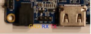
The UART pins are located between HDMI and power jack of the board. On some boards they are marked as TX, RX and GND on the PCB (simplified layout: ..DC-IN.. [GND][RX][TX] ..HDMI..). Just attach some leads according to our UART Howto.
Default settings for U-boot and Linux console are 115200bps, 8N1.
Pictures
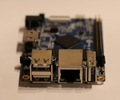
Orange Pi PC
Orange Pi PC Plus
Variants
- The Orange Pi PC Plus adds 8GB eMMC and Realtek RTL8189FTV SDIO-based WiFi directly on the board (as opposed to a soldered-on module). The physical dimensions and position of connectors are exactly the same as the Orange Pi PC. The same type of DRAM is used but tracing is different since one DRAM module moved to the bottom side of the PCB. Since a FEL button is missing on this board it's not that easy to verify DRAM reliability the usual way (through FEL boot) so we should stay with the failsafe value of 624 MHz DRAM clock. Regarding software support we can base on fex file and device tree for the PC and simply add the necessary WiFi chip mappings.
Also known as
See also
- Xunlong Orange Pi site
- Official Github Repository.
- Official Orange Pi Forums.
- H3_Manual_build_howto
- Orange Pi PC Schematics 1.2
- Orange Pi PC Plus Schematics 1.1
Manufacturer images
- A various amount of prebuilt images is provided via OrangePi's Website most of them not containing latest fixes.
- Many people are also running images generated by forum user loboris (mirror available). It should be noted that when using loboris' images it's always useful to execute his update_kernel.sh to get latest kernel fixes and settings for the board in question (various script.bin variants for different Orange Pis and display settings). To adjust script.bin settings (overclocked/overvolted) to linux-sunxi defaults there's informations and a script available in this thread.
