Xunlong Orange Pi 2
| Xunlong Orange Pi 2 | |
|---|---|
 | |
| Manufacturer | OrangePi |
| Dimensions | 93mm x 60mm |
| Release Date | March 2015 |
| Website | Orange Pi 2 Product Page |
| Specifications | |
| SoC | H3 @ 1.3 GHz |
| DRAM | 1GiB DDR3 @ 600MHz |
| NAND | no nand available |
| Power | DC 5V @ 2A (via DC input) |
| Features | |
| Video | HDMI output with HDCP, HDMI CEC, HDMI 30 function, Integrated CVBS, simultaneous output of HDMI and CVBS |
| Audio | 3.5 mm Jack and HDMI |
| Network | 10/100Mbps Ethernet(RJ45), WiFi (Realtek RTL8189ETV, IEEE 802.11 b/g/n) |
| Storage | TF card(Max 64GB)/MMC card slot |
| USB | 4 USB2.0 Host, 1 USB2.0 OTG |
| Other | CIR |
| Headers | 1 pin UART, 3 pin UART, LCD/ LVDS, CSI, 40 pin GPIO |
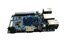
Orange Pi 2 is H3 based development board produced by Xunlong. The concept is based on the original Orange Pi. Both, Orange Pi 2 and its smaller cousin Orange Pi Mini 2 (similar to Orange Pi Mini) were released in March 2015. The board is based on a quad-core H3 CPU, and offers a TF card slot, onboard Ethernet (10/100M Ethernet RJ45) and WiFi (802.11 b/g/n), 40 pin GPIO and 4 x USB type A connectors, but does not come with the SATA port like the A20 based original Orange Pi did.
Identification
The PCB has the following silkscreened on it:
Orange Pi 2
Sunxi support
Current status
The H3 SoC support has matured since its introduction in kernel 4.2. Most of the board functionality for boards such as Orange Pi 2 are available with current mainline kernels. Some features (hw accelerated crypto, hw spinlocks, and thermal) are still being worked on. For a more comprehensive list of supported features, see the status matrix for mainline kernels. In addition, legacy 3.4 kernels are available in various work-in-progress git branches.
See the Manual build section for more details.
Manual build
You can build things for yourself by following our Manual build howto and by choosing from the configurations available below.
U-Boot
Mainline U-Boot
Use the orangepi_2 (supported since v2016.05) build target. The U-Boot repository and toolchain is described in the Mainline U-Boot howto.
The H3 boards can boot from SD cards, eMMC, NAND or SPI NOR flash (if available), and via FEL using the OTG USB port. In U-Boot, loading the kernel is also supported from USB or ethernet (netboot). HDMI support in U-Boot is still WIP.
Linux Kernel
Sunxi/Legacy Kernel
The 3.4 kernel from the official Allwinner's git repository does not support H3 yet. But it is possible to use one of the kernel forks, based on the lichee H3 SDK tarball:
- Siarhei Siamashka's branch '20151207-embedded-lima-memtester-h3'
- Yann Dirson's fork added a few more fixes and adopted most of
- Boris Lovosevic' great initial work on Allwinner's H3 kernel
Configure this kernel using sun8i_h3_defconfig, the rest is explained in the kernel compilation guide.
Use the .fex file for generating script.bin. The .fex file can be found here for now orangepi2.fex. This was extracted from the android sdcard image.
When booting the legacy 3.4 kernel with the mainline U-Boot, add the following line to boot.cmd:
  setenv machid 1029
  setenv bootm_boot_mode sec
Some other legacy kernel repositories:
- 3.4-lichee-based kernel, based on work by ssvb and loboris
- Yocto support here glues together all the required parts to get this kernel to work with mainline u-boot, as well as accelerated X11/GLES support
- A newer H3 BSP variant appeared with tons of fixes which has been made available by FriendlyARM.
- A cleaned up fork has been adopted by Armbian project. On top of that Armbian maintains a bunch of 3.4.x patches for H3 devices.
Mainline kernel
The mainline kernel has good support for the H3 SoC. Please refer to the status matrix for a more detailed list of the development process, links to patches and links to kernel fork repositories. Minor drivers that are currently work-in-progress may require a) third party patches (see also arm-linux mailing list) or b) a pre-patched distro (e.g. Armbian).
Repositories with H3 patches:
- Ondřej Jirman's branch for H3 based orange Pi (kernel 4.19) (work-in-progress DVFS)
- Thermal regulation (if CPU heats above certain temperature, it will try to cool itself down by reducing CPU frequency)
- HDMI audio support (from Jernej Skrabec)
- Configure on-board micro-switches to perform system power off function
- Wireguard (https://www.wireguard.com/)
- Philipp Rossak's THS patches (in the sunxi-ths- branches)
- Corentin Labbe's HW Crypto and spinlock patches (in respective branches)
Use the sun8i-h3-orangepi-2.dtb device-tree binary.
Tips, Tricks, Caveats
FEL mode
The button marked SW3, located between the HDMI and TTL UART, triggers FEL mode when pressed during boot.
To verify you have successfully entered FEL mode, check the output of fel version. For the Orange Pi 2, it should look like:
AWUSBFEX soc=00001680(unknown) 00000001 ver=0001 44 08 scratchpad=00007e00 00000000 00000000
LEDs
For those with a transparent case (or no case at all) the Orange Pi 2's LED activity is good. The red power LED (D7) can be turned off.
Expansion Ports
The Orange Pi 2 exposes a 2.54mm pitch connector.
| Extension Header | |||
|---|---|---|---|
| 1x40 Header | |||
| 1 | 3.3V | 2 | VCC-5V |
| 3 | PA12 (TWI0-SDA/DI_RX/EINT12) | 4 | VCC-5V |
| 5 | PA11 (TWI0-SCK/DI_TX/EINT11) | 6 | GND |
| 7 | PA6 (SIM_PWREN/PWM1/PA_EINT6) | 8 | PA13 (SPI1_CS/UART3_TX/PA_EINT13) |
| 9 | GND | 10 | PA14 (SPI1_CLK/UART3_RX/PA_EINT14) |
| 11 | PA1 (UART2_RX/JTAG_CK0/PA_EINT1) | 12 | PD14(RGMII_NULL/MII_TXERR/RMII_NULL) |
| 13 | PA0 (UART2_TX/JTAG_MS0/PA_EINT0) | 14 | GND |
| 15 | PA3 (UART2_CTS/JTAG_DI0/PA_EINT3) | 16 | PC4 (NAND_CE0) |
| 17 | 3.3V | 18 | PC7 (NAND_RB1) |
| 19 | PC0 (NAND_WE/SPI0_MOSI) | 20 | GND |
| 21 | PC1 (NAND_ALE/SPI0_MISO) | 22 | PA2 (UART2_RTS/JTAG_DO0/PA_EINT2) |
| 23 | PC2 (NAND_CLE/SPI0_CLK) | 24 | PC3 (NAND_CE1/SPI0_CS) |
| 25 | GND | 26 | PA21 (PCM0_DIN/SIM_VPPPP/PA_EINT21) |
| 27 | PA19 (PCM0_CLK/TWI1_SDA/PA_EINT19) | 28 | PA18 (PCM0_SYNC/TWI1_SCK/PA_EINT18) |
| 29 | PA7 (SIM_CLK/PA_EINT7) | 30 | GND |
| 31 | PA8 (SIM_DATA/PA_EINT8) | 32 | PG8 (UART1_RTS/PG_EINT8) |
| 33 | PA9 (SIM_RST/PA_EINT9) | 34 | GND |
| 35 | PA10 (SIM_DET/PA_EINT10) | 36 | PG9 (UART1_CTS/PG_EINT9) |
| 37 | PA20 (PCM0_DOUT/SIM_VPPEN/PA_EINT20) | 38 | PG6 (UART1_TX/PG_EINT6) |
| 39 | GND | 40 | PG7 (UART1_RX/PG_EINT7) |
Adding a serial port
Locating the UART
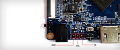
The UART pins are located on J3 between DC input and Uboot Button(SW3) of the board. They are marked as TX, RX and GND on the PCB. Just attach some leads according to our UART Howto.
Pictures
Variants
- The original Orange Pi was released in November 2014. The Orange Pi features a standard TF card slot and a 26 pin GPIO connector (similar to the Raspberry Pi A/B).
- The smaller cousin Orange Pi Mini 2 (similar to Orange Pi Mini) were also released in March 2015.
Also known as
See also
There are several websites about Orange Pi 2 and claiming to support it. It has to be clarified, what is "official" and who is behind this sites.
- Xunlong Orange Pi site
- "Official" Github Repository.
- "Official" Orange Pi Form.
- H3_Manual_build_howto.
Currently only an android image for an sdcard is provided via OrangePi's Website.


