YuzukiHD Avaota A1
| YuzukiHD Avaota A1 | |
|---|---|
 | |
| Manufacturer | YuzukiHD Open Hardware |
| Dimensions | 100mm x 75mm x 24mm |
| Release Date | 2024 |
| Website | Device Product Page |
| Specifications | |
| SoC | T527 @ 1.8Ghz |
| DRAM | 1GiB/2GiB/4GiB LPDDR4 @ 1200MHz |
| NAND | 16/32/64/128 GiB eMMC |
| Power | DC 12V @ 3A |
| Features | |
| LCD | 240x135 (1.14" 16:9) |
| Video | HDMI (Type A - full), DP |
| Audio | 3.5mm headphone plug, HDMI |
| Network | WiFi 6 2.4+5GHz (Manufacturer device), 2 * 10/100/1000Mbps Ethernet (Realtek RTL8211F) |
| Storage | µSD, eMMC |
| USB | 1 USB2.0 Host, 1 USB2.0 Type-C OTG, 1 USB 3.0 OTG |
| Headers | 40pin GPIO, CAN, fan, MIPI-CSI, LCD |
This page needs to be properly filled according to the New Device Howto and the New Device Page guide.
Open Hardware router board with two Gigabit Ethernet interfaces, WiFi 6, one USB 3.0 port and a small LCD screen for status messages.
Identification
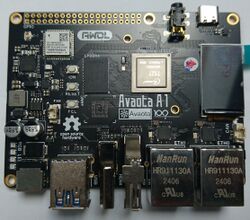
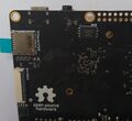
The PCB features the "Avaota A1" name prominently in the middle, above the Avaota logo. On the underside, on the bottom left corner, close to the Ethernet jacks, it shows the hardware version number.
The latest version so far is v1.7.
Sunxi support
Current status
Mainline support is WIP, the board is the primary bringup vehicle for the A523 SoC support.
Manual build
You can build things for yourself by following our Manual build howto and by choosing from the configurations available below.
Mainline U-Boot
Not yet supported, DRAM code not ready yet, though being worked on.
Preliminary U-Boot proper support with working USB and MMC has been done, for loading mainline kernels. Syterkit is an Open Source project which contains a blob to do the critical DRAM initialisation, and can then be used to load a mainline U-Boot proper build or kernels directly.
Mainline Linux Kernel
Not yet supported, but patches are on the list.
Tips, Tricks, Caveats
Add MANUFACTURER DEVICE specific tips, tricks, Caveats and nice to have changes here.
FEL mode
The FEL button triggers FEL mode.
Device specific topic
If there are no further device specific topics to add, remove these sections.
...
Accessing the serial port
The boot console is connected to pins on the 40pin GPIO header connector, in the same location as on the Raspberry Pi 2: pin 6 for TX, pin 8 for TX, pin 4 for GND. It's the usual 3.3V TTL level, refer to the UART howto for more details.
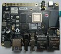
Pictures
Schematic
hardware info (gerber, layout, BOM, schematics for all versions.
Also known as
Pine64 also produces and sells the board, using the original name.
See also
Add some nice to have links here. This includes related devices, and external links.
Manufacturer images
Official AvaotaOS releases, based on the BSP kernel.


