Xunlong Orange Pi Zero Plus 2
| Xunlong Orange Pi Zero Plus 2 | |
|---|---|
 | |
| Manufacturer | OrangePi |
| Dimensions | 46mm x 48mm |
| Release Date | March 2017 |
| Website | Orange Pi Zero Plus 2 Product Page |
| Specifications | |
| SoC | H3 / H5 |
| DRAM | 512 MiB DDR3 |
| Power | DC 5V via µUSB or pin headers |
| Features | |
| Video | HDMI, CVBS on pin headers |
| Audio | microphone, stereo line-out on pin headers |
| Network | AP6212 Wi-Fi sdio-id:02D0:A9A6 |
| Storage | µSD, 8GB eMMC on board |
| USB | 1 USB 2.0 OTG, 2 x USB 2.0 on pin headers |
| Other | CIR on pin headers |
| Headers | 3 pin UART, 26 + 13 pin GPIO |
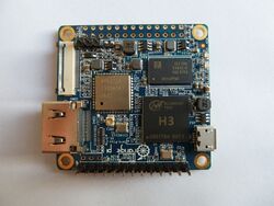
Orange Pi Zero Plus 2 and Orange Pi Zero Plus 2 H5 are development boards produced by Xunlong. Orange Pi Zero Plus 2 is based on H3 SoC while the H5 version uses H5.
Identification
The PCB has the following silkscreened on it:
Orange Pi Zero Plus 2 V1.0
Sunxi support
Current status
The H3 SoC support has matured since its introduction in kernel 4.2. Most of the board functionality for boards such as Orange Pi Zero Plus 2 are available with current mainline kernels. Some features (hw accelerated crypto, hw spinlocks, and thermal) are still being worked on. For a more comprehensive list of supported features, see the status matrix for mainline kernels. In addition, legacy 3.4 kernels are available in various work-in-progress git branches.
See the Manual build section for more details.
Manual build
You can build things for yourself by following our Manual build howto and by choosing from the configurations available below.
U-Boot
Mainline U-Boot
Use the orangepi_zero_plus2_defconfig (H5 version supported since v2017.07) / orangepi_zero_plus2_h3_defconfig (H3 version supported since v2020.01) build target. The U-Boot repository and toolchain is described in the Mainline U-Boot howto.
The H3 boards can boot from SD cards, eMMC, NAND or SPI NOR flash (if available), and via FEL using the OTG USB port. In U-Boot, loading the kernel is also supported from USB or ethernet (netboot). HDMI support in U-Boot is still WIP.
Linux Kernel
Sunxi/Legacy Kernel
The 3.4 kernel from the official Allwinner's git repository does not support H3 yet. But it is possible to use one of the kernel forks, based on the lichee H3 SDK tarball:
- Siarhei Siamashka's branch '20151207-embedded-lima-memtester-h3'
- Yann Dirson's fork added a few more fixes and adopted most of
- Boris Lovosevic' great initial work on Allwinner's H3 kernel
Configure this kernel using sun8i_h3_defconfig, the rest is explained in the kernel compilation guide.
Use the .fex file for generating script.bin. Partially supported but an Armbian legacy image with nearly full hardware support already exists.
When booting the legacy 3.4 kernel with the mainline U-Boot, add the following line to boot.cmd:
  setenv machid 1029
  setenv bootm_boot_mode sec
Some other legacy kernel repositories:
- 3.4-lichee-based kernel, based on work by ssvb and loboris
- Yocto support here glues together all the required parts to get this kernel to work with mainline u-boot, as well as accelerated X11/GLES support
- A newer H3 BSP variant appeared with tons of fixes which has been made available by FriendlyARM.
- A cleaned up fork has been adopted by Armbian project. On top of that Armbian maintains a bunch of 3.4.x patches for H3 devices.
Mainline kernel
The mainline kernel has good support for the H3 SoC. Please refer to the status matrix for a more detailed list of the development process, links to patches and links to kernel fork repositories. Minor drivers that are currently work-in-progress may require a) third party patches (see also arm-linux mailing list) or b) a pre-patched distro (e.g. Armbian).
Repositories with H3 patches:
- Ondřej Jirman's branch for H3 based orange Pi (kernel 4.19) (work-in-progress DVFS)
- Thermal regulation (if CPU heats above certain temperature, it will try to cool itself down by reducing CPU frequency)
- HDMI audio support (from Jernej Skrabec)
- Configure on-board micro-switches to perform system power off function
- Wireguard (https://www.wireguard.com/)
- Philipp Rossak's THS patches (in the sunxi-ths- branches)
- Corentin Labbe's HW Crypto and spinlock patches (in respective branches)
Use the sun50i-h5-orangepi-zero-plus2.dtb (H5 version) / sun8i-h3-orangepi-zero-plus2.dtb (H3 version) device-tree binary.
Expansion Port
The Orange Pi Zero Plus 2 has a 26-pin, 0.1" unpopulated connector with several low-speed interfaces. It's marketed as Raspberry Pi-compatible.
Table below is based on Xunlong's board schematic and product page.
| 2x13 Header | |||
|---|---|---|---|
| 1 | 3.3V | 2 | 5V |
| 3 | TWI0_SDA / PA12 / GPIO12 | 4 | 5V |
| 5 | TWI0_SCK / PA11 / GPIO11 | 6 | GND |
| 7 | PWM1 / PA06 / GPIO6 | 8 | UART2_TX / PA00 / GPIO0 |
| 9 | GND | 10 | UART2_RX / PA01 / GPIO1 |
| 11 | S-TWI-SCK / PL0 / GPIO352 | 12 | PD11 / GPIO107 |
| 13 | S-TWI-SDA / PL1 / GPIO353 | 14 | GND |
| 15 | UART2_CTS / PA03 / GPIO3 | 16 | TWI1-SDA / PA19 / GPIO19 |
| 17 | 3.3V | 18 | TWI1-SCK / PA18 / GPIO18 |
| 19 | SPI1_MOSI / PA15 / GPIO15 | 20 | GND |
| 21 | SPI1_MISO / PA16 / GPIO16 | 22 | UART2_RTS / PA02 / GPIO2 |
| 23 | SPI1_CLK / PA14 / GPIO14 | 24 | SPI1_CS / PA13 / GPIO13 |
| 25 | GND | 26 | PD14 / GPIO110 |
The Orange Pi Zero Plus 2 has another 13-pin, 0.1" header with several low-speed interfaces.
TODO: This table was taken from the Orange Pi Zero's wiki page as the Orange Pi Zero Plus 2 details are still . It's probably the same for the Zero Plus 2 (the Xunlong's datasheet and product pages seem to agree). Use at your own risk.
| 1x13 Header | |
|---|---|
| 1 | 5V |
| 2 | GND |
| 3 | USB-DM2 |
| 4 | USB-DP2 |
| 5 | USB-DM3 |
| 6 | USB-DP3 |
| 7 | LINEOUTR |
| 8 | LINEOUTL |
| 9 | TV-OUT |
| 10 | MIC-BIAS |
| 11 | MIC1P |
| 12 | MIC1N |
| 13 | CIR-RX |
Tips, Tricks, Caveats
Powering the board
Unlike most other Orange Pi boards, the Orange Pi Zero Plus 2 can be powered through the Micro USB jack (being a normal USB OTG port otherwise) or via one of the Expansion Port pin headers (using 5V/GND pins).
There is no power on/off switch or reboot switch on the board.
FEL Mode
The Orange Pi Zero Plus 2 runs the standard Allwinner BootROM when the SoC starts up. There are no buttons or connectors to select FEL mode so the BootROM will only enter FEL mode if a special SD card is present or if there are no valid boot options. For example if there is no boot option on the SPI NOR chip and no SD card is present then plugging the board's micro-USB port into a USB port on a PC will show up as a FEL device. Using Sunxi tools and issuing:
$ sunxi-fel ver
shows:
AWUSBFEX soc=00001680(H3) 00000001 ver=0001 44 08 scratchpad=00007e00 00000000 00000000
Onboard eMMC
An 8GB onboard eMMC is present and supported by the Armbian image.
Benchmark: iozone -e -I -a -s 100M -r 4k -r 16k -r 512k -r 1024k -r 16384k -i 0 -i 1 -i 2
                                                             random    random
             kB  reclen    write  rewrite    read    reread    read     write
         102400       4     5350     5923    12191    12233     9453     5861
         102400      16    17258    19735    28225    27445    24999    18945
         102400     512    36332    34508    59980    60008    59936    33483
         102400    1024    34079    35472    61459    61508    61546    33952
         102400   16384    36899    36954    67638    67631    67605    36413
LEDs
The board has two LEDs next to DRAM:
- A green LED, connected to PL10.
- A red LED, connected to PA17.
Camera
vip_dev0_power_en = PA08
USB header
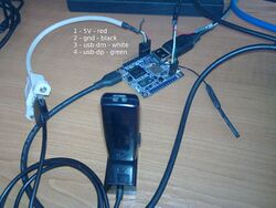
To make a trivial adapter you can use "pc case usb port" but you will need to rearrange the pins:
1 - 5V - red 2 - GND - black 3 - dm - white 4 - dp - green
JTAG
TODO
Adding a serial port
Locating the UART
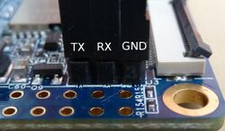
The UART pins are located next to unpopulated 26-pin header on the board. They are marked as TX, RX and GND on the PCB with barely visible letters. Just attach some leads according to our UART Howto.
Pictures
Variants
- Currently two variants of the Orange Pi Zero Plus 2 boards exist - one with H3 and the other with H5 SoC. Otherwise the boards seem identical.
Also known as
See also
- opi0+2h3 schematics File:ORANGE PI-ZERO-PLUS2 V1 0.pdf
- Xunlong Orange Pi site
- Official Github Repository
- Official Orange Pi Forums


