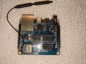
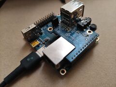
Xunlong Orange Pi Zero2
| Xunlong Orange Pi Zero2 | |
|---|---|
| Manufacturer | Xunlong |
| Dimensions | 53mm x 60mm |
| Release Date | Nov 2020 |
| Website | Orange Pi Zero2 |
| Specifications | |
| SoC | H616 @ 1.512 Ghz |
| DRAM | 1GiB DDR3 @ 720 MHz (2 * Samsung K4B4G1646E-BYMA) |
| Power | DC 5V @ 2A via USB-C connector |
| Features | |
| Video | Micro HDMI 2.0a, CVBS on header |
| Audio | Line out on header, HDMI audio |
| Network | WiFi 802.11 a/b/g/n (AW859A), 10/100/1000Mbps Ethernet (Realtek 8211F)D |
| Storage | µSD, 16Mbit SPI flash |
| USB | 1 X USB2.0 Host, 1 X USB2.0 OTG, 2 X USB2.0 Host on header |
| Other | Accelerometer (Manufacturer device), GPS, IRDA |
| Headers | UART, JTAG, LCD, VGA, ... |
Not to be confused with Zero Plus 2 (H5) This is the H616 version (2020)
This page needs to be properly filled according to the New Device Howto and the New Device Page guide.
Identification
A serial number sticker can be found on the back of the board:
PI Zero2 - H616
SerialNumber
The PCB has a version number silkscreened nest to the SOC and RAM:
Orange Pi
Zero2 v1.3
General Notes
As usual, the board is shipped with an empty SPI flash, so won't boot anything unless an SD card is installed. The power LED is software controlled, so also won't light up.
Ubuntu Focal image provided by vendor installs and boots to Armbian with no issues. Quick first pass looks good, although some pinmux and regulator logs will probably have to be addressed first.
I have uploaded consoles to capture the starting point with this board.
Sunxi support
Current status
The Orange Pi Zero2 is used as the bringup vehicle for the H616 SoC mainline effort. Linux kernel support was officially merged in v6.0 (adding the devicetree files), although basic support was already in v5.12. Trusted-Firmware supports the SoC since v2.5 (May 2021), U-Boot support was merged into v2021.04-rc1.
Images
BSP
Allwinner H616 Android with Kernel 4.9
Manual build
You can build things for yourself by following our Manual build howto and by choosing from the configurations available below.
U-Boot
Use the orangepi_zero2_defconfig build target. Available since v2021.04-rc1.
Linux Kernel
Use the sun50i-h616-orangepi-zero2.dtb device-tree binary from a mainline kernel, available since v6.0.
Expansion ports
The Orange Pi Zero2 has a 26-pin, 0.1" populated connector with several low-speed interfaces.
The primary function follows loosely the old Raspberry Pi pin assignment (TWI3 (aka I2C), UART5, SPI1, GPIOs), but pinmuxing gives access to more interfaces (not all at the same time): UART2 (incl. h/w handshake), TWI2, TWI4, SPDIF, PWM1, PWM2, single bit MMC2.
| 2x13 Header | ||||||||
|---|---|---|---|---|---|---|---|---|
| 3.3V | 1 | 2 | 5V | |||||
| SPI1_CS0 / UART2_TX | PH5 | I2C3-SDA | 3 | 4 | 5V | |||
| SPDIF_OUT | PH4 | I2C3-SCK | 5 | 6 | GND | |||
| PC9 | GPIO-73 | 7 | 8 | UART5-TX | PH2 | SPDIF_CLK / PWM2 / TWI2_SCK | ||
| GND | 9 | 10 | UART5-RX | PH3 | PWM1 / TWI2_SDA | |||
| SCD2_CMD | PC6 | GPIO-70 | 11 | 12 | GPIO-75 | PC11 | ||
| SDC2_CLK | PC5 | GPIO-69 | 13 | 14 | GND | |||
| PC8 | GPIO-72 | 15 | 16 | GPIO-79 | PC15 | SPI0_WP | ||
| 3.3V | 17 | 18 | GPIO-78 | PC14 | ||||
| UART2_RTS / TWI4_SDA | PH7 | SPI1-MOSI | 19 | 20 | GND | |||
| UART2_CTS | PH8 | SPI1-MISO | 21 | 22 | GPIO-71 | PC7 | ||
| UART2_RX / TWI4_SCK | PH6 | SPI1-SCK | 23 | 24 | SPI1-CS | PH9 | ||
| GND | 25 | 26 | GPIO-74 | PC10 | SCD2_D0 | |||
The Orange Pi Zero2 has another 13-pin, 0.1" header with USB and analogue interfaces. The 13-pin interface board originally used for Orange Pi Zero is compatible with Zero2, but the microphone on the board is no longer available.
| 1x13 Header | |
|---|---|
| 1 | 5V |
| 2 | GND |
| 3 | USB2-DM |
| 4 | USB2-DP |
| 5 | USB3-DM |
| 6 | USB3-DP |
| 7 | LINEOUTR |
| 8 | LINEOUTL |
| 9 | TV-OUT |
| 10 | PC1 |
| 11 | PI16 |
| 12 | PI6 |
| 13 | CIR-RX / PH10 |
Tips, Tricks, Caveats
FEL mode
No dedicated FEL button. FEL mode will be entered without an SD card and with no valid eGON signature on the SPI flash (which is empty on arrival). Alternatively the usual FEL trigger SD card image can be used.
The USB-C connector used to power the board carries the USB-OTG signals for the FEL mode, so the board needs to be powered through a host computer or a powered USB hub for using FEL mode.
LEDs
There are two unlabelled LEDs on the board, a red and a green one. According to the schematic they are Power (red) and Status (green), but both are connected to GPIOs (PC12 and PC13), so need active software toggling to light up.
SPI booting
The board contains a 2MB SPI NOR flash chip (located on the underside of the board), and the SoC can boot firmware from there. The BOOT_MODE bit in the SID is cleared, to let GPIO pins determine the boot order. So to enable booting from SPI flash (after the micro-SD card has been tried), pull PC5 to GND, by bridging pins 9 and 13 on the expansion port header. U-Boot supports SPI booting since v2023.01-rc1.
Serial port
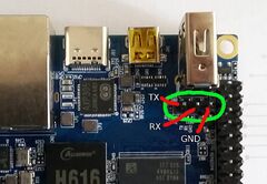
The UART pins are located behind the USB port on the board. They are marked as TX, RX and GND on the PCB. Just attach some leads according to our UART Howto.


