Tanix TX1
| Tanix TX1 | |
|---|---|
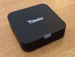 | |
| Manufacturer | Tanix |
| Dimensions | 58mm x 58mm x 25mm |
| Release Date | November 2023 |
| Website | Tanix TX1 |
| Specifications | |
| SoC | H313 @ 1.3Ghz |
| DRAM | 1GiB/2GiB LPDDR3 @ 720MHz |
| eMMC | 8/16GB |
| Power | DC 5V @ 2A |
| Features | |
| Video | HDMI (Type A - full) |
| Audio | 3.5mm headphone plug, HDMI |
| Network | WiFi 802.11 b/g/n (SCI S9082H) |
| Storage | eMMC, NO SD card! |
| USB | 1 USB2.0 Host |
| Other | infrared |
| Headers | UART pads |
This page needs to be properly filled according to the New Device Howto and the New Device Page guide.
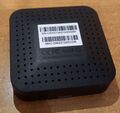
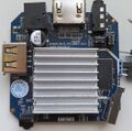
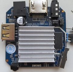
Tiny TV box (about 70% of a credit card), without SD card and Ethernet. AXP313 PMIC.
Identification
On the top of the device, it shows the Tanix logo. On the bottom of the device, there is nothing really device specific, it just shows a sticker with the serial number and MAC address, below some compliance logos, and "DC = 5V/2A MADE IN CHINA".
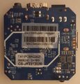
The PCB has the following silkscreened on it:
CS_H313_TX1_EMCP_V1.1
DATE:2023-09-21
In android, under Settings->About Tablet, you will find:
- Model Number: TX1
- Build Number: '
Sunxi support
Current status
Supported in both mainline kernel and U-Boot.
Manual build
You can build things for yourself by following our Manual build howto and by choosing from the configurations available below.
Mainline U-Boot
Use the tanix_tx1_defconfig build target. Available since v2024.10-rc3.
Mainline Linux Kernel
Use the sun50i-h313-tanix-tx1.dtb devicetree binary from a mainline kernel, available since v6.10. Older kernels with decent H616 support will work as well, as long as you give it the right DTB, for instance the one used in U-Boot ($fdtcontroladdr).
Tips, Tricks, Caveats
FEL mode
Use a toothpick or any other non-conductive stick to push the button inside the A/V connector when powering up the box. Connect a USB-A/USB-A cable to the only USB port and a host PC.
Adding a serial port (voids warranty)
Device disassembly
Insert some spudger tool into the small gap around the top of the device, and gently pry the lid off by moving the tool around the entire lid. There is some sticky heat dispensing material glued to the lid, which presses on top of the PCB heat spreader, but that comes off easily. A similar sticky pad holds the PCB on the bottom shell, so just use some tool to lever and pull the PCB out off the device, its not secured with any screws.
Locating the UART
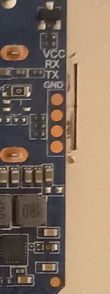
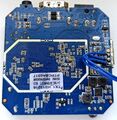
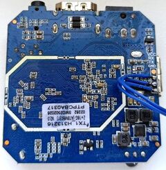
The UART pads are on the underside of the PCB, there are four circular solder pads just underneath the USB connector. The silk screen label above them describes them as "VCC, RX, TX, GND", as usual just use the lower three to connect some cable and ignore the VCC pin. Also see the UART howto.
Pictures
Also known as
- Wudung W01
- Vontar QTV Q1
See also
Manufacturer images
No known images available for download (yet?).
