T95H
| T95H | |
|---|---|
 | |
| Manufacturer | Shenzhen Nanxiangzi Technology Co. Ltd |
| Dimensions | 100mm x 100mm x 19mm |
| Release Date | Month year |
| Website | Device Product Page |
| Specifications | |
| SoC | H616 @ 1.512Ghz |
| DRAM | 1GiB/2GiB/4GiB DDR3 @ xxxMHz |
| eMMC | 8/16/64GB |
| Power | DC 5V @ 2A |
| Features | |
| Video | HDMI (Type A - full), CVBS |
| Audio | 3.5mm AV plug, HDMI |
| Network | WiFi: 802.11 b/g/n (XRadio XR819); 10/100Mbps Ethernet (Internal) |
| Storage | µSD, eMMC |
| USB | 2 USB2.0 Host |
| Other | IRDA |
| Headers | UART |
This page needs to be properly filled according to the New Device Howto and the New Device Page guide.
If a device is special, then feel free to provide a terse description of what makes this device so special. But terse, no novels, no marketing blurb.
Identification
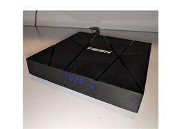
The top has an "T95H" logo embossed in the centre
On the bottom of the device, the following is printed on a sticker:
T95H
RAM:1GB ROM:8GB
The PCB has the following silkscreened on it:
H616 - T95MAX - V4.0
In android, under Settings->About, you will find:
- Model Number: MBOX
- Build Number: 10.1.XH23
Sunxi support
Current status
Not yet supported, but U-Boot and kernel support WIP. Since it uses the AC200 integrated 100MBit Ethernet PHY, it relies on pending mainline support for the chip to have working Ethernet.
Manual build
You can build things for yourself by following our Manual build howto and by choosing from the configurations available below.
Mainline U-Boot
Mainline Linux Kernel
Tips, Tricks, Caveats
Add MANUFACTURER DEVICE specific tips, tricks, Caveats and nice to have changes here.
FEL mode
The button on the top of the PCB triggers FEL mode mode (to be confirmed). It is reachable through the CVBS connector..
Device specific topic
If there are no further device specific topics to add, remove these sections.
...
Adding a serial port (voids warranty)
To get access to the UART pads, you have to open the box.
Device disassembly
To open up the case, the pins can be easily popped with a thin screw driver or the Plastic tool howto.
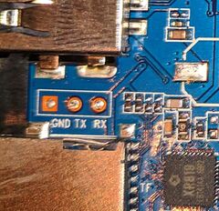
Locating the UART
The UART pads are located on the bottom left of the device PCB, between USB 0 the sdcard socket, providing RX, TX and GND signals, as pictured. The assignment is printed next to it. To solder some wires or pins, just remove the PCB (three screws). To route the wires outside the case, you could drill a small hole anywhere to the right on the pcb where there is an empty space in the case. Once done, follow the UART howto.
Pictures
Schematic
List schematics, board layout, cad files, etc here.
Also known as
List rebadged devices here.
See also
Add some nice to have links here. This includes related devices, and external links.
Manufacturer images
Optional. Add non-sunxi images in this section.


