Sunchip CX-A99
| Sunchip CX-A99 | |
|---|---|
| {{{image}}} | |
| Manufacturer | Shenzhen Sunchip Technology Co., Ltd |
| Dimensions | 164mm x 164mm x 29mm (excluding antenna) |
| Release Date | November 2014 |
| Website | Please refer to the list of known products using this board |
| Specifications | |
| SoC | A80: 4 x ARM Cortex-A15 cores @ 1.8 GHz + 4 x ARM Cortex-A7 cores @ 1.2 GHz. |
| DRAM | 1 GiB/2 GiB/4 GiB DDR3 @ 600 MHz (Samsung 531 K4B8G1646Q-MYK0 EKF53490) |
| eMMC | 8/16/32 GB (Samsung 422 KLMBG4WEBC-B031 N6HC7A8K) |
| Power | DC 12V @ 2A |
| Features | |
| Video | HDMI (Type A - full), composite |
| Audio | composite, HDMI, SPDIF |
| Network | IEEE 802.11 b/g/n/ac Wifi + Bluetooth (Ampak AP6335), 10/100/1000Mbps Ethernet (Realtek RTL8211E) |
| Storage | 1 x SD or 1 x µSD, 1 x SATA (externally) through an on-board JMicron JM20329 SATA to USB bridge. |
| USB | 2 x USB2.0 Host, 1 USB3.0 OTG |
| Other | Receiver for infrared remote control |
| Headers | 1 x UART (internally) |
This page needs to be properly filled according to the New Device Howto and the New Device Page guide.
This board is used in at least five similar Android TV box products. So far all known products with this board use eMMC as storage, but the board is prepared for use of NAND flash instead of eMMC.
Identification
In FEL mode, the device show up as "1f3a:efe8 Onda (unverified) V972 tablet in flashing mode" in lsusb.
In android, under Settings->About Tablet, you will find:
- Model Number: DEVICE
- Build Number: SOC_BOARD_DEVICE_*.*
After opening the case, a sticker with the text CX-A99 becomes visible on the Ethernet connector. The main PCB has "A99-V1.1" and "2014-12-15" printed on it next to the Ethernet connector.
Sunxi support
Current status
Sunxi/Legacy kernel and U-Boot
Like all A80 based devices, there is no support in u-boot-sunxi. Like all A80 based devices, there is no support in our sunxi kernel.
Mainline kernel and U-Boot
Device Tree file and some of the missing drivers are in progress. The table below generally refers to what is supported in the development branch, possibly with WIP patches as explained in the section «Manual build».
| Chip or function | Kernel driver | U-Boot driver | Device Tree compatible | Notes | |
|---|---|---|---|---|---|
| AC100 | container | mfd/ac100.c | no | x-powers,ac100 | |
| Audio codec | no | x-powers,ac100-codec | |||
| Real-time clock | rtc/rtc-ac100.c | x-powers,ac100-rtc | |||
| AP6335 | IEEE 802.11 Wifi | net/wireless/broadcom/brcm80211/brcmfmac/ | no | - | Requires additional firmware and configuration file. |
| Bluetooth | TBD | TBD | |||
| FM receiver | TBD | TBD | It is unknown if this part is even wired on the board. | ||
| AXP808 | container | mfd/axp20x-rsb.c, mfd/axp20x.c | WIP | x-powers,axp808 | See warning above. Uses device tree compatible x-powers,axp806 for the Linux kernel 4.9 and 4.10 series. |
| regulators | regulator/axp20x-regulator.c | ||||
| DRAM | Max 3.5 GiB | 2.0 GiB detected and enabled | - | Kernel crashes with LPAE enabled which is required to access the last 0.5 GiB. | |
| eMMC/SD | config | clk/sunxi/clk-sun9i-mmc.c | mmc/sunxi_mmc.c | allwinner,sun9i-a80-mmc-config-clk | |
| clock | clk/sunxi/clk-mod0.c | allwinner,sun9i-a80-mmc-clk | |||
| data | mmc/host/sunxi-mmc.c | allwinner,sun9i-a80-mmc | |||
| LEDs | leds/leds-gpio.c | led/led_gpio.c | gpio-leds | Requires AXP808 regulators aldo2 and cldo1 to be enabled for the LEDs to light up. | |
| OZ80120 | regulator/gpio-regulator.c | no | regulator-gpio | Voltage regulator for the Cortex-A15 cluster. The kernel driver currently glitches the output during initialisation, causing a crash if the system boots up on a Cortex-A15 core. | |
| SATA (JM20329) | usb/storage/ | cmd/usb_mass_storage.c (depends on USB support) | - | Data sheet. The SATA-to-USB bridge only shows up on the USB bus when a SATA device is connected. Also, some unknown magic is necessary after power-up to activate it. As a workaround, run the vendor U-Boot once after power-up. | |
| UART | tty/serial/8250/8250_dw.c | serial/ns16550.c | snps,dw-apb-uart | ||
| USB 2.0 | power (Vbus) | regulator/fixed.c | usb/host/ehci-sunxi.c (but needs AXP808 support to power up the ports) | regulator-fixed | OHCI is not used because the SOC ports are permanently connected to on-board USB high-speed devices. |
| data | usb/host/ehci-platform.c | allwinner,sun9i-a80-ehci and generic-ehci | |||
| PHY | phy/phy-sun9i-usb.c | allwinner,sun9i-a80-usb-phy | |||
| clocks | clk/sunxi-ng/ccu-sun9i-a80-usb.c | no | allwinner,sun9i-a80-usb-clks | ||
| hub (GL850G) | usb/core/hub.c | common/usb_hub.c (depends on USB support) | - | Data sheet. Ports 3 and 4 don't seem to be connected to anything. | |
Images
HW-Pack
BSP
Manual build
First of all, you should read the Mainline U-Boot and Mainline Kernel Howto. For example, the instructions below assume that you know what to add to the commands if you're cross-compiling.
Where the instructions below say «curl», you can use «wget -O -» instead. Both commands will download the given URL and output it to stdout.
U-Boot
V2016.11 release
This is the first usable release on A80 devices. However, support is limited to serial console, eMMC, SD card and 2 GB of DRAM.
 git clone --origin denx --branch v2016.11 git://git.denx.de/u-boot.git
 cd u-boot
 git checkout -b v2016.11-cx-a99
Development branch
This is where support for more parts of the board will appear first.
 git clone --origin denx-sunxi --branch next git://git.denx.de/u-boot-sunxi.git
 cd u-boot-sunxi
 git branch --move next next-cx-a99
Experimental SMP support
There is experimental support for using all four Cortex-A7 cores:
 git remote add -f wens https://github.com/wens/u-boot-sunxi.git
 git cherry-pick 29e0cfb4f77f7aa369136302cee14a91e22dca71..45777442bdb03337a1d8337ea0e57ca9181dfd08
 git cherry-pick 2d9a3452e8d83f38e0d891f3e769bde387c1f429..f205e09885fea23622e0c1aac43b531fa6795607
(There's also a later follow-up posting explaining issues which prevent the Cortex-A15 cores from being put into service.)
Device tree file (U-Boot)
The mmc1 port used for the SDIO Wifi module is missing from the A80 device tree file, so the board's device tree won't compile. Apply the patch for it:
curl https://patchwork.kernel.org/patch/9401759/mbox/ | git am -p4 --directory arch/arm
Add the device tree file for the board:
curl https://patchwork.kernel.org/patch/9563791/mbox/ | git am -C0 -p4 --directory arch/arm
U-Boot configuration
The configuration is very simple at the moment because so few devices are supported:
 cat <<'end-of-config' >configs/Sunchip_CX-A99_defconfig
CONFIG_ARM=y
CONFIG_ARCH_SUNXI=y
CONFIG_MACH_SUN9I=y
CONFIG_DRAM_CLK=600
CONFIG_DRAM_ZQ=3881915
CONFIG_DRAM_ODT_EN=y
CONFIG_MMC0_CD_PIN="PH17"
CONFIG_MMC_SUNXI_SLOT_EXTRA=2
CONFIG_DEFAULT_DEVICE_TREE="sun9i-a80-cx-a99"
CONFIG_SPL=y
# CONFIG_CMD_IMLS is not set
# CONFIG_CMD_FLASH is not set
# CONFIG_CMD_FPGA is not set
end-of-config
make Sunchip_CX-A99_defconfig
U-Boot build
make all
Linux kernel
Stable series 4.9
Get yourself a copy of the Linux 4.9.9 (or later) release.
 git clone --origin stable --branch linux-4.9.y git://git.kernel.org/pub/scm/linux/kernel/git/stable/linux-stable.git
 cd linux-stable
 git branch --move linux-4.9.y stable-4.9-cx-a99
The mmc1 port used for the SDIO Wifi module was missing from the A80 device tree file. Apply the patch for it:
curl https://patchwork.kernel.org/patch/9401759/mbox/ | git am
Note: Releases before 4.9.9 need a patch to prevent damage to the DRAM chips through over-voltage.
curl https://patchwork.kernel.org/patch/9530319/mbox/ | git am
Proceed to adding the device tree file and kernel configuration.
Mainline series 4.10
Get yourself a copy of the Linux 4.10-rc7 (or later) release.
 git clone --origin mainline git://git.kernel.org/pub/scm/linux/kernel/git/torvalds/linux.git linux-mainline
 cd linux-mainline
 git branch --move master mainline-4.10-cx-a99
Note: Releases before 4.10-rc7 need a patch to prevent damage to the DRAM chips through over-voltage.
curl https://patchwork.kernel.org/patch/9530319/mbox/ | git am
Proceed to adding the device tree file and kernel configuration.
Development series
You should use the sunxi-next branch in the linux-sunxi repository. If you're starting from scratch, this will get you started:
 git clone --origin sunxi --branch sunxi-next https://github.com/linux-sunxi/linux-sunxi.git
 cd linux-sunxi
 git branch --move sunxi-next cx-a99
If you already have another linux kernel repository cloned, you can just add the linux-sunxi one:
 git remote add -f sunxi https://github.com/linux-sunxi/linux-sunxi.git
 git checkout -b cx-a99 remotes/sunxi/sunxi-next
In both cases, you should now have a local branch cx-a99 which tracks the upstream sunxi-next branch and you should have all the source code checked out.
Next step is to apply the patches to support the AXP808 power management IC on the board:
 curl https://patchwork.kernel.org/patch/9563795/mbox/ | git am
 curl https://patchwork.kernel.org/patch/9563781/mbox/ | git am
 curl https://patchwork.kernel.org/patch/9563787/mbox/ | git am
 curl https://patchwork.kernel.org/patch/9563789/mbox/ | git am
Device tree file
This part is common to the Linux 4.9, 4.10 and development series (4.11) kernels.
curl https://patchwork.kernel.org/patch/9563791/mbox/ | git am -C2
Kernel configuration
The kernel includes two configurations that are useful as a starting point.
- multi_v7_defconfig
- This is probably the best bet for beginners as it is intended for OS distributions to use and includes many commonly used drivers, file system and so on.
- make multi_v7_defconfig
- sunxi_defconfig
- This is a somewhat minimalistic configuration where you definitely will want to add more options yourself.
- make sunxi_defconfig
Two configuration fixes need to be applied. multi_v7_defconfig builds the RSB bus driver and consequently the regulator support as modules. They should instead be built into the kernel. Also, neither configuration enables the driver for the AC100 real-time clock by default. This will be fixed in the Linux 4.12 series.
 sed -i -e 's/\(CONFIG_\(SUNXI_RSB\|REGULATOR_AXP20X\|MFD_AXP20X.*\)=\)m/\1y/' .config
 echo -e 'CONFIG_MFD_AC100=y\nCONFIG_RTC_DRV_AC100=y' >> .config
make menuconfig # or xconfig or whatever you prefer
Finish off by building the kernel, modules and device tree blob:
make zImage modules dtbs
Tips, Tricks, Caveats
FEL mode
The button on the underside of the board triggers FEL mode. This button can be accessed through a hole in the bottom of the case (i.e. without disassembling the device). See vendor instructions.
Use the file FES _FES_1-0000000000 from the manufacturer image for SPL/boot0 when booting over USB.
Note: To turn off power to the board, you will need to unplug the cable from the USB OTG port in addition to disconnecting the 12 V supply. Otherwise, the board may well continue to run on just the 5 V supplied through the USB connector.
Device disassembly
Unscrew each of the four screws under the rubber pad in each corner of the bottom of the case. The case can now be opened carefully.
Unscrew the screw holding the small board with red/blue led and IR receiver to the top part of the case.
Unscrew the screw holding the ground wire to the top part of the case.
Unscrew the four screws holding the main PCB to the top part of the case.
Carefully unplug the antenna cable from the main PCB. The main PCB can now be removed from the case.
Locating the UART (serial console port)
Opposite of the SD or micro-SD card slot, there is a 5-pin header, with a small, white triangle pointing to pin 1. The pinout is:
- 1 Ground.
- 2 Ground.
- 3 +3.3 V.
- 4 UART0 RX input (GPIO pin PH13) with 3.3 V levels.
- 5 UART0 TX output (GPIO pin PH12) with 3.3 V levels.
TIP: When logged into the console, use the stty command to set a terminal size that matches that of your terminal window, e.g. "stty columns 262 rows 78", so your screen will not become messed up.
Wifi firmware
You need firmware and a data file for the firmware. The data file is on the Android root partition:
 # mkdir --parents /mnt/android-root
 # mkdir --parents /lib/firmware/brcm
 # mount --read-only /dev/disk/by-path/platform-1c11000.mmc-part7 /mnt/android-root
 # cp -p /mnt/android-root/vendor/modules/nvram_ap6335.txt /lib/firmware/brcm/brcmfmac4339-sdio.txt
 # umount /mnt/android-root
The firmware can be downloaded from the kernel.org firmware repository:
 # cd /lib/firmware/brcm
 # curl --xattr --remote-time --remote-name https://git.kernel.org/cgit/linux/kernel/git/firmware/linux-firmware.git/plain/brcm/brcmfmac4339-sdio.bin
or
# wget --timestamping https://git.kernel.org/cgit/linux/kernel/git/firmware/linux-firmware.git/plain/brcm/brcmfmac4339-sdio.bin
A/V cable
There are reports that you need an A/V cable with a plug length of 17 mm instead of the usual 14 mm. The ground ring is 3 mm longer than usual. Pinout is as usual: Tip is composite video, ring 1 and ring 2 are analog audio and ring 4 is ground.
Hardware details
Power routing
Default voltages are taken from sys_config1.fex, which also provides most of the information in this section.
- 12 V from DC input jack
- SATA connector 12 V
- NX5AA ? 5 V switching mode regulator (always on)
- SATA connector 5 V
- 3 * AT6280B switch
- 3 * USB connector
- X-Powers AXP808 switching mode (dcdcN) and linear (XldoN) regulators
- aldo1 (default: 3.0 V, on)
- aldo2 (default: 1.8 V, on)
- Pin group G
- Pin group M
- Audio (supply "aldo2")
- Wireless Ethernet/Bluetooth I/O (supply 2)
- aldo3 (default: 2.5 V, on)
- Pin group A
- Wired Ethernet (supply 1)
- bldo1 (default: 1.8 V, on)
- DLLs and PLLs? (system hangs if turned off)
- bldo2 (default: 0.9 V, on)
- CPUS? (system hangs if turned off)
- bldo3 (default: 1.2 V, off)
- USB HSIC port
- bldo4 (default: 1.1 V, on)
- cldo1 (default: 3.3 V, on)
- Pin group L (controls regulators for USB 2.0 ports and Cortex-A15 cores)
- LEDs
- cldo2 (default: 3.3 V, off) (wired in parallel with cldo3)
- Wireless Ethernet/Bluetooth supply 0
- cldo3 (default: 3.3 V, off) (wired in parallel with cldo2)
- Wireless Ethernet/Bluetooth supply 1
- dcdca (default: 0.9 V, on)
- 4 * ARM Cortex-A7 cores
- dcdcb (default: 1.5 V, on)
- DRAM
- dcdcc (default: 0.9 V, off)
- PowerVR GPU?
- dcdcd (default: 0.9 V, on)
- SYS? (system hangs immediately if turned off)
- dcdce (default: 3.3 V, on)
- Pin group B
- Pin group C
- Pin group D
- Pin group E
- Pin group F
- Pin group H
- eMMC
- SD card slot power pin
- Serial console port power pin
- SPDIF
- sw0 (default: off)
- Audio (supply "sw0")
- Composite video output (GM7122)
- Wired Ethernet (supply 0)
- OZ80120 switching mode regulator (default: 0.9 V, on)
- 4 * ARM Cortex-A15 cores
- AMS1117 3.3 V linear regulator (always on) (Datasheet link but site down as of 2016-07-04)
- JM20329 pins 5 VCCO, 10 AVDDH, 16 AVDDH, 18 AVDDH, 42 VCCO.
- JM20329 pin 9 AVREG output (internal 1.8 V regulator) connected to pins 23 AVDDL, 36 VCCK, 44 VCCK.
A80 pins
The following information was mainly extracted from the vendor's sys_config.fex file.
| Pin | Used for | Voltage range for logic high |
|---|---|---|
| PA0 - PA5, PA7 - PA10, PA12 - PA17 | IEEE 802.3 Ethernet controller | ? |
| PB0 - PB17 | - | ? |
| PC6 - PC16 | eMMC card (mmc2) | 1.8 V - 3.3 V |
| PD0, PD3 - PD7, PD10 - PD12, PD24, PD26 - PD27 | Composite video out | ? |
| PE0 - PE17 | - | ? |
| PF0 - PF4 | SD card (mmc0) | 1.8 V - 3.3 V |
| PG0 - PG5 | IEEE 802.11 wireless Ethernet (mmc1) | 1.8 V - 3.3 V |
| PG6 - PG9 | Bluetooth (uart2) | 1.8 V - 3.3 V |
| PG10 | Blue LED (normal) | 1.8 V - 3.3 V |
| PG11 | Red LED (standby) | 1.8 V - 3.3 V |
| PH6 | sprite? (output) | ? |
| PH0 - PH1 | I²C 0 | ? |
| PH2 - PH3 | I²C 1 | ? |
| PH12 - PH13 | Serial console (uart0) | ? |
| PH15 | USB 3.0 Vbus enable | ? |
| PH16 | recovery key? (input) | ? |
| PH17 | SD card detect (mmc0) | ? |
| PH18 | S/PDIF output | ? |
| PL1 | Audio output power amplifier enable | ? |
| PL2 - PL5 | OZ80120 voltage regulator output control | ? |
| PL6 | Infrared remote control receiver | ? |
| PL7 | USB 2.0 Vbus enable for the connector next to the 12 V jack | ? |
| PL8 | USB 2.0 Vbus enable for the connector next to the SD card slot | ? |
| PL9 | Audio interrupt input (from AC100) | ? |
| PM0 | IEEE 802.11 wireless Ethernet power enable and reset disable | ? |
| PM1 | IEEE 802.11 wireless Ethernet interrupt input | ? |
| PM2 | Bluetooth interrupt input | ? |
| PM3 | Bluetooth reset disable | ? |
| PM4 | Bluetooth wake-up output | ? |
| PN0 - PN1 | Reduced Serial Bus | ? |
Pictures
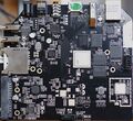
Top side of main PCB (with heat sink removed) from a Tronsmart Draco AW80 Telos device.
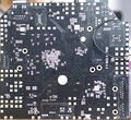
Bottom side of main PCB from a Tronsmart Draco AW80 Telos device.


Also known as
Products using eMMC as storage:
- Instabox Fantasy A8 (site down as of 2016-08-09) (no external antenna)
- Jesurun CS-Q8 (ships with larger remote control)
- Jesurun Maxone
- Rikomagic (RKM) MK80/MK80LE
- Tronsmart Draco AW80 Meta/Telos
See also
Manufacturer images
The archives can be extraced with e.g. The Unarchiver. You can then use awimage from awutils to unpack the image.
| Model | Rikomagic MK80 | Tronsmart Draco AW80 |
|---|---|---|
| Archive | MK80_151012.rar | Draco_AW80_SDK3.0_151117.zip |
| Image file name | MK80_4.4_151012.img | Draco AW80_Andriod-5.0_20150317.img |
| 12345678_1234567890BOOT_0 | Boot0 4.0.0 for SD/MMC boot | |
| FES _FES_1-0000000000 | Boot0 ?.?.? for FEL/USBBoot | |
| 12345678_UBOOT_0000000000 | U-Boot 2011.09-rc1-00003-g0db9686 (Sep 16 2015 - 01:08:04) | U-Boot 2011.09-rc1-00003-g9097903 (Sep 14 2015 - 06:04:57) |
| RFSFAT16_ENV_FEX000000000 | U-Boot environment variables | |
| RFSFAT16_BOOT_FEX00000000 | Normal Android bootimg, kernel (0x20008000), ramdisk (0x21000000), page size: 2048 | |
| RFSFAT16_RECOVERY_FEX0000 | Recovery Android bootimg, kernel (0x20008000), ramdisk (0x21000000), page size: 2048 | |
| RFSFAT16_SYSTEM_FEX000000 | Android root file system as Android sparse image | |
| COMMON _SYS_CONFIG100000 | sys_config.fex | |
Extracting sys_config.fex
(Note: This is only of interest if you want to construct a Device Tree file for e.g. mainline U-Boot and mainline kernel.)
It is easy to extract it from one of the manufacturer images. Note that the Ubuntu image made by Tronsmart does not contain a correct version of this file.
Once you have root on the Android system, you can also extract the file from eMMC card partition 10:
sed -n -e '/;A80 PAD/ s/.*;A80 PAD/;A80 PAD/' -e '/^;A80 PAD/,/^cpu7/ p' /dev/mmcblk2p10 >sys_config.fex
Booting from (micro)SD card
The A80 Boot ROM will look for a boot loader at offset 8 kB into the card, load 32 kB of that into memory and execute it. You can install a boot loader from the files in a manufacturer image file. Replace $1 in the commands below with the device which holds your SD card - consider using /dev/disks/by-id to avoid mistakes.
dd bs=1024 seek=8 if='12345678_1234567890BOOT_0' of="$1"
dd bs=1024 seek=19096 if='12345678_UBOOT_0000000000' of="$1"
This requires your partitions to stay clear of the two areas above, and you should also keep the legacy and mainline U-Boot card layout in mind. You can create a suitable partition table with GNU Parted:
parted --script "$1" -- mklabel msdos mkpart primary fat32 1024kiB 19096kiB mkpart primary ext2 24MiB -1s quit
This gives you a 17 MB /boot partition for e.g. kernel images and the remaining part of the card above 24 MiB as root partition.
(Partitions should be aligned to an SD card allocation unit for good write speed. 24 MB will work for allocation units of 1 MB, 2 MB, 3 MB, 4 MB, 6 MB, 8 MB, 12 MB and 24 MB. Write speed on the /boot partition is not important, however, so it need not be aligned.)