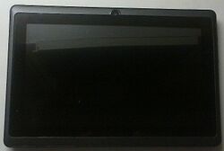
Sencor Element 7 V3
| Sencor Element 7 V3 | |
|---|---|
 | |
| Manufacturer | Sencor |
| Dimensions | 182mm x 121mm x 11mm |
| Release Date | April 2013 |
| Website | Device Product Page |
| Specifications | |
| SoC | A13 @ 1Ghz |
| DRAM | 512MiB DDR3 @ 384MHz (Elpida J2108BCSE-DJ-F) |
| NAND | 4GB |
| Power | DC 5V @ 1.5A, 3250mAh 3.7V Li-Pol battery |
| Features | |
| LCD | 800x480 (7" 16:9) |
| Touchscreen | 5-finger capacitive (Silead GSL1680) |
| Audio | 3.5mm headphone plug, internal speaker, internal microphone |
| Network | WiFi 802.11 b/g/n (Ralink RT5370N) |
| Storage | µSD |
| USB | USB2.0 OTG |
| Camera | 0.3MPx (640x480) front |
| Other | Accelerometer (Freescale MMA7660) |
| Headers | UART |
Sencor Element 7 version 3 is a standard Q8 format, A13 based tablet.
Identification
On the back of the device, the following is printed:
element 7
version 3

SENCOR®
Internet Tablet with 7" Capacitive display
and 4GB Memory
The PCB has the following silkscreened on it:
SAQ8-A13 V1.2
In android, under Settings->About Tablet, you will find:
- Model Number: ELEMENT 7V3
- Build Number: nuclear_evb-eng 4.0.4 GC0308_5370_1680_7660_MSM
Sunxi support
Current status
Supported, but lacks mainline kernel support and likely some driver support in sunxi kernel.
Manual build
You can build things for yourself by following our Manual build howto and by choosing from the configurations available below.
U-Boot
Sunxi/Legacy U-Boot
Use the q8_a13_tablet build target.
Mainline U-Boot
Use the q8_a13_tablet build target.
Linux Kernel
Sunxi/Legacy Kernel
Use the sencor_element7v3.fex file.
Mainline kernel
Use the sun5i-a13-sencor-element7v3.dts device-tree binary.
Tips, Tricks, Caveats
FEL mode
Either Vol+ or Vol- button triggers FEL mode. Simply hold the button and then connect to the USB port.
No success entering Boot1 for me, but ./fel version, LiveSuit/PhoenixSuit flashing and booting over USB works fine.
Hardware problems
The device is of typical cheap chinese quality, so if you happen to be already inside it playing god, it may be worthwhile to check for hardware problems.
Adding a serial port (voids warranty)
Device disassembly
Identical with Q8 Format disassembly. To access the PCB backside, unplug the three flex cables and unscrew the three PH0 screws. Turn the board over on the battery, then remove the plastic cover glued to the backside.
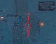
Locating the UART
UART solder pads are in the middle on the back-side of the PCB. Device's TX is the one closer to the USB port.
Note 1: I am receiving no output during boot or Boot0 FEL mode; only serial_noise seems to work for me. It maps to /dev/ttyS1 (so it needs editing the script.bin or the kernel arguments).
Note 2: The diagnostic pads are easily torn off from the PCB (maybe not suitable for soldering to).
If despite those caveats you decide to try for yourself, here's how: UART howto.


