PocketBook Basic Lux 4 (PB618)
| PocketBook Basic Lux 4 (PB618) | |
|---|---|
 | |
| Manufacturer | PocketBook |
| Dimensions | width161.3 x breadth108 x height8 |
| Release Date | 2023 |
| Website | Device Product Page |
| Specifications | |
| SoC | B288 @ 1Ghz |
| DRAM | 512MiB DDR3L @ 1866MHz |
| NAND | 8GB KLM8G1GETF-B041 |
| Power | 1300mAh battery |
| Features | |
| LCD | 758x1024 (X" X:Y) |
| Touchscreen | 2-finger self-capacitive (FocalTech FT6336U) |
| Video | proprietary eInk display / ED060XCH |
| Audio | none |
| Network | WiFi 802.11 b/g/n (Manufacturer device) |
| Storage | nand/eMMC KLM8G1GETF-B041, µSD(external) |
| USB | X USB2.0 Host, 1 USB2.0 OTG |
| Camera | none |
| Other | eInk "backlight", AXP227 |
| Headers | UART, TWI |
This page needs to be properly filled according to the New Device Howto and the New Device Page guide.
If a device is special, then feel free to provide a terse description of what makes this device so special. But terse, no novels, no marketing blurb.
Identification
On the back of the device, the following is printed:
Model No.: PB618
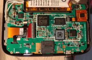
The PCB has the following silkscreened on it:
XRZ_E159-PB618 main V1.0 20230115
Sunxi support
Current status
Currently no support
Images
Optional. Add MANUFACTURER DEVICE specific sunxi ROM images here. E.g. a livesuit image or some other linux image which uses linux-sunxi code. Do not put non-sunxi images here, they should live under See also. If no sunxi based images are available, this section can be removed.
HW-Pack
Optional. Add MANUFACTURER DEVICE sunxi HW-pack specifics here. When empty, this section can be removed.
BSP
Optional. Add MANUFACTURER DEVICE sunxi BSP specifics here. When empty, this section can be removed.
Manual build
You can build things for yourself by following our Manual build howto and by choosing from the configurations available below.
U-Boot
Sunxi/Legacy U-Boot
Legacy B288 U-Boot uploaded by PocketBook:
https://github.com/pocketbook/uboot_b288
My fork with fixed compilation and Boot0 modifications to init DRAM:
https://github.com/Soupborsh/uboot_b288
Mainline U-Boot
There is almost zero support. I am absolute noob but I created a U-Boot fork which can be booted through FEL.
What works:
- UART
- GPIO (seems to work, can toggle pins)
- I2C (Currently bus 2 does not work)
- USB maybe??
Booting from FEL:
- Init DRAM (see #FEL_mode)
sunxi-fel write 0x4a000000 u-boot-dtb.binsunxi-fel execute 0x4a000000
Linux Kernel
Sunxi/Legacy Kernel
Legacy B288 3.10.65 kernel uploaded by PocketBook:
https://github.com/pocketbook/kernel-b288
My fork with fixed compilation:
https://github.com/Soupborsh/kernel-b288
Touchscreen proprietary binary module does not work with it. I booted kernel using preinstalled U-Boot.
Mainline kernel
Use the FAMILY-CHIP-DEVICE.dtb device-tree binary.
Tips, Tricks, Caveats
Preinstalled U-Boot shell/monitor entry
On the step where you need to press power button 3 times to enter FEL, press it less than 3 times and type into UART many times CTRL+C and many other characters. U-Boot should then enter it's shell/monitor and you should see it display interrupts.
Emmc works, however, if you use mmc command it stops for some reason. IIRC You can use fatls, ls and similar, as well as, there was a command to enter USB Mass Storage Mode but it is for /boot partition only.
FEL mode
Way that doesn't rely on emmc contents(probably unsafe):
- Remove protective metal shield on PCB
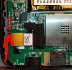
- Connect smd thing that probably goes to probably emmc clock from side of CPU to ground(it is PC4 gpio pin)
- Power on
Intended by the manufacturer way:
- Connect device to pc by USB
- Power off device
- Press and hold central home button, do not release
- Press power on button once to power on, and then 3 more times to enter FEL mode
- You can release central home button now, your device should be now in FEL mode
Here is what UART outputs during this:
[     0.270]HELLO ;) BOOT0 is starting!
[     0.280]AXP22 Voff=3.3V
[     0.283]fel flag  = 0x00000000
[     0.292]DRAM: 512
[     0.311]MMC3 v5.1 HSDDR52/DDR50 8 bit 7456 MB
[     0.361]Entry_name        = u-boot
[     0.369]Entry_name        = soc-cfg
[     0.373]Entry_name        = dtb
[     0.377]Jump to u-boot


U-Boot 2014.07-hg78e7bb6939f0 (Aug 08 2023 - 15:56:03) Allwinner Technology , Build: 78e7bb6939f0

normal mode
i2c_init: by cpux
[      0.397]pmbus:   ready
[      0.412]PMU: AXP221
[      0.412]PMU: AXP22X found
[      0.413]PMU: dcdc2 1260
[      0.415]IC Version: 1(0:A 1:B 2:other)
[      0.418]PMU: pll1 1008 Mhz,PLL6=600 Mhz
AXI=336 Mhz,AHB=100 Mhz, APB1=50 Mhz
dcdc1_vol = 3000, onoff=1
dcdc2_vol = 1260, onoff=1
dcdc3_vol = 1800, onoff=0
dcdc4_vol = 1100, onoff=1
dcdc5_vol = 1350, onoff=1
aldo1_vol = 3000, onoff=0
aldo2_vol = 1800, onoff=1
aldo3_vol = 3000, onoff=1
dldo1_vol = 1800, onoff=1
dldo2_vol = 3300, onoff=0
dc1sw_vol = 3300, onoff=0
dc5ldo_vol = 1100, onoff=0
DRAM:  512 MiB
fdt addr: 0x56ddc0f8
gd->fdt_size: 0x11ec0
Relocation Offset is: 15f3b000
gic: normal mode
[      0.534]MMC:        3
[mmc]: mmc driver ver 2016-08-01 13:45:00
[mmc]: get sdc_ex_dly_used 2, use auto tuning sdly
[mmc]: card3 io is 1.8V.
[mmc]: get sdc3 sdc_tm4_hs200_max_freq 100.
[mmc]: get sdc3 sdc_tm4_hs400_max_freq 100.
SUNXI SD/MMC: 3
[mmc]: 50 MHz...
[mmc]: sample: 52 - 192(ps)
[mmc]: ds: 50 - 200(ps)
[mmc]: 100 MHz...
[mmc]: sample: 26 - 192(ps)
[mmc]: ds: 25 - 200(ps)
[mmc]: media type 0x8000000
[mmc]: host caps: 0x1ef
[mmc]: MMC3: v5.1 HSSDR52/SDR25 50MHz 8 bit 7456 MB
[mmc]: already at HSSDR52_SDR25 mode
[mmc]: EOL Info(Rev blks): Normal
[mmc]: Wear out(type A): 0%-10% life time used
[mmc]: Wear out(type B): 0%-10% life time used
[      0.613]sunxi flash init ok
Using default environment

bootcmd set setargs_mmc
vbus pc exist, limit to pc
Bus:2 VBat:4232 Ratio:100
Disable PF0-PF5
SW fel:   1
VBUS req: 0
KEYCOUNTER:1
KEYCOUNTER:2
Entering FEL
set next system status
sunxi_board_close_source
[mmc]: MMC Device 2 not found
[mmc]: mmc 2 not find, so not exit
[mmc]: mmc exit start
[mmc]: 50 MHz...
[mmc]: sample: 51 - 196(ps)
[mmc]: ds: 51 - 196(ps)
[mmc]: 100 MHz...
[mmc]: sample: 26 - 192(ps)
[mmc]: ds: 25 - 200(ps)
[mmc]: mmc 3 exit ok
reset cpu
[     0.270]HELLO ;) BOOT0 is starting!
[     0.280]AXP22 Voff=3.3V
[     0.282]fel flag  = 0x5aa5a55a
[     0.286]eraly jump fel
DRAM is not initialized.
DRAM initialization is WIP, we can execute modified Boot0 to init DRAM and return to FEL.:
1.Build My Boot0 fork:
2.Set FEL flag:
sunxi-fel writel 0x1C20508 0x5AA5A55A
3.Load and execute boot0.img(result of building Boot0)
sunxi-fel spl boot0.img
4.Wait for about 20 seconds, and the attempt running some FEL commands(sunxi-fel readl 0x1C20508 for example) until they do not fail.
5. Your device should be in FEL with initialized DRAM. If it did not work, you can try again(sometimes it does not work for me).
AXP227
AXP227 seems to be same as AXP221 but with address 34, even Boot0 says AXP221 to it. SCL and SDA pins seem to be in the same place. I watched them with my logic analyzer. I can manually write to registers(using U-Boot's i2c command) specifed in AXP221 wiki and it works here(at least dldo2 and "REG 12h: Regulator output control").
Adding a serial port (voids warranty)
Follow UART howto, there are 3 pads shown in the photo, solder wires to them. UART is 3.3V and 115200 8N1(default for many programs, such as minicom.)
Device disassembly
See Plastic tool howto. Back panel can be removed using plastic tool, it pops out. Power connector needs to be lifted up(be careful, I am not sure because I had to apply a lot of force), other connectors can be disconnecting by gently lifting the thing that fixes in place the ribbon cable, and then ribbon cable can be disconnected from motherboard easily since nothing holds them. Motherboard can be removed by unscrewing 4 screws holding it then sliding slightly in the direction to SD card hole(I refer to it as downwards) because there are some metal things that hold it on top, then carefully remove ribbon cables through holes to not tear them apart. Screen removing is untested.
Pictures
Take some pictures of your device, upload them, and add them here. DO NOT UPLOAD PICTURES WHICH YOU PLUCKED OFF THE INTERNET.
Schematic
By toggling GPIO pins and looking at fex file, I identified some pins(hopefully correct), look at the image.
P.S: I will later upload my Krita file.
Also known as
List rebadged devices here.
See also
KLM8G1GETF-B041 eMMC datasheet
Files to understand the device better:
Kernel dts: sun8iw10p1.dtsi sun8iw10p1-pinctrl.dtsi sun8iw10p1-clk.dtsi
and many others in sources.
Manufacturer images
Optional. Add non-sunxi images in this section.


