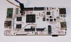
LinkSprite pcDuino3
| LinkSprite pcDuino3 | |
|---|---|
 | |
| Manufacturer | LinkSprite |
| Dimensions | 125mm x 66mm x heightmm |
| Release Date | April 2014 |
| Website | Device Product Page |
| Specifications | |
| SoC | A20 @ 1Ghz |
| DRAM | 1GiB DDR3 @ 480MHz |
| NAND | 4GB |
| Power | DC 5V @ 2A (micro-USB) |
| Features | |
| Video | HDMI (Type A, full) |
| Audio | 3.5mm headphone plug, HDMI |
| Network | WiFi 802.11bgn (Realtek RTL8188EUS), 10/100Mbps Ethernet (IC+ IP101A) |
| Storage | µSD, SATA |
| USB | 1 USB2.0 Host, 1 USB2.0 OTG |
| Other | IR |
| Headers | UART, LVDS connector, Arduino-compatible headers |
Identification
On the back of the board, it helpfully reads "pcDuino Dual core".
Sunxi support
Current status
Supported.
There are even patches for mainline on the Mailing list. These provide basic board support, along with USB and SATA.
Images
HW-Pack
BSP
Manual build
- For building u-boot, use the "pcduino3" target.
- The .fex file can be found in sunxi-boards as linksprite_pcduino3.fex
Everything else is the same as the manual build howto.
Mainline kernel
Use the sun7i-a20-pcduino3.dts device-tree file for the mainline kernel.
In order to make ethernet work for pcDuino3b, you will have to edit the device-tree file: simply copy &gmac{...} section from sun7i-a20-pcduino3-nano.dts to sun7i-a20-pcduino.dts.
Tips, Tricks, Caveats
FEL mode
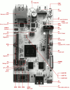
The UPGRADE/SW2 button triggers FEL mode.
Expansion headers
SPI0 pins are wired to both: P7 and J8 pins. SPI0 clock is additionally wired to LED_CLK.
| Pin number | pcDuino name | Sunxi name |
|---|---|---|
| 1 | TX (Square Pad) | PB23 |
| 2 | GND | |
| 3 | RX | PB22 |
| Pin number | pcDuino name | Sunxi name |
|---|---|---|
| 1 | GPIO14 | PH11 |
| 2 | GPIO15 | PH12 |
| 3 | GPIO16 | PH13 |
| 4 | GPIO17 | PH14 |
| pcDuino name | Sunxi name |
|---|---|
| LED 1 - Power LED | |
| LED 2 - Wifi LED | |
| LED RX | PH15 |
| LED RX | PH16 |
| LED CLK / SPI0_CLK / GPIO13 | PI11 |
| pcDuino name | Sunxi name |
|---|---|
| SW1 - Reset | |
| SW2 - Upgrade | FEL mode |
| SW3 - BACK | PH17 |
| SW4 - HOME | PH18 |
| SW5 - MENU | PH19 |
| Pin number | pcDuino name | Sunxi name |
|---|---|---|
| 1 | SPI1_MISO / GPIO12 | PC22 |
| 2 | +5V DC / SPI1 GPIO20 / GPIO20 | PC19 |
| 3 | SPI1_CLK / GPIO13 | PC20 |
| 4 | SPI1_MOSI / GPIO11 / PWM11 | PC21 |
| 5 | RESET | |
| 6 | GND |
| Pin number | pcDuino name | Sunxi name |
|---|---|---|
| 1 | SPI0_MISO / GPIO12 | PI13 |
| 2 | +5V DC | |
| 3 | SPI0_CLK / GPIO13 | PI11 |
| 4 | SPI0_MOSI / GPIO11 / PWM11 | PI12 |
| 5 | RESET | |
| 6 | GND |
| Pin number | pcDuino name | Sunxi name |
|---|---|---|
| 1 | A0 | |
| 2 | A1 | |
| 3 | A2 | |
| 4 | A3 | |
| 5 | A4 | |
| 6 | A5 |
| Pin number | pcDuino name | Sunxi name |
|---|---|---|
| 1 | GPIO0 / UART2_RX | PI19 |
| 2 | GPIO1 / UART2_TX | PI18 |
| 3 | GPIO2 | PH7 |
| 4 | GPIO3 / PWM3 | PH6 |
| 5 | GPIO4 | PH8 |
| 6 | GPIO5 / PWM5 | PB2 |
| 7 | GPIO6 / PWM6 | PI3 |
| 8 | GPIO7 | PH9 |
| Pin number | pcDuino name | Sunxi name |
|---|---|---|
| 1 | not connected | |
| 2 | IOREF | |
| 3 | RESET | |
| 4 | 3.3V DC output | |
| 5 | 5V DC output | |
| 6 | GND | |
| 7 | GND | |
| 8 | +5V in |
| Pin number | pcDuino name | Sunxi name |
|---|---|---|
| 1 | GPIO8 | PH10 |
| 2 | GPIO9 / PWM9 | PH5 |
| 3 | SPI0_SS / GPIO10 / PWM10 | PI10 |
| 4 | SPI0_MOSI / GPIO11 / PWM11 | PI12 |
| 5 | SPI0_MISO / GPIO12 | PI13 |
| 6 | SPI0_CLK / GPIO13 | PI11 |
| 7 | GND | |
| 8 | AREF | |
| 9 | TWI2_SDA | PB21 |
| 10 | TWI2_SCL | PB20 |
Adding a serial port
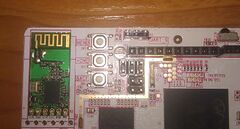
There is a 3pin 2.54mm pitch header near the wifi module, called "UART_0" (P3 - Debug Port). All you have to do is attach some jumper wires according to our UART howto.
Pictures
Variants
At some point in 2015, Linksprite started selling an updated variant of the pcDuino V3 called pcDuino v3B (or pcDuino3B). Compared to the original board, v3B updated the ethernet connection to Gigabit Ethernet. Other than that, the board layout stayed the same.


