Jesurun Q5
| Jesurun Q5 | |
|---|---|
 | |
| Manufacturer | Jesurun |
| Dimensions | 100mm x 100mm x 24mm |
| Release Date | August 2013 |
| Website | Unknown |
| Specifications | |
| SoC | A10 @ 1Ghz |
| DRAM | 1GiB DDR3 @ 312MHz (4x PE918-15E) |
| NAND | 8GB |
| Power | DC 5V @ 2A |
| Features | |
| Video | HDMI (Type A - full, female) |
| Audio | 3.5mm headphone plug, HDMI, SPDIF |
| Network | WiFi 802.11 g (Realtek RTL8188CTV), 10/100Mbps Ethernet (Realtek RTL8201CP) |
| Storage | µSD |
| USB | 2X USB2.0 Host |
| Headers | UART, IRDA |
This page needs to be properly filled according to the New Device Howto and the New Device Page guide.
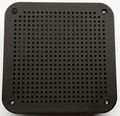
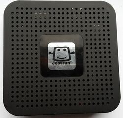
The Jesurun Q5 is a cheap A10 based media puck, with a distinctive case with the top and bottom panels consisting almost entirely of ventilation holes.
Identification
Apart from a Jesurun sticker, there are no external markings.
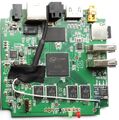
The PCB has the following silkscreened on it:
AVM STV301 MB V1.1
2012.07.16
Find out the strings as reported under settings.
In android, under Settings->About Tablet, you will find:
- Model Number: DEVICE
- Build Number: SOC_BOARD_DEVICE_*.*
Sunxi support
Current status
U-boot-sunxi and linux-sunxi are supported.
Images
HW-Pack
BSP
Manual build
- For building u-boot, use the jesurun_q5_defconfig target.
- The .fex file can be found in sunxi-boards as sys_config/a10/jesurun-q5.fex
Everything else is the same as the manual build howto.
Mainline U-Boot
For building mainline u-boot, use the jesurun_q5_defconfig target.
Mainline kernel
Use the sun4i-a10-jesurun-q5.dts device-tree file for the mainline kernel.
NOTE: submitting patch is WIP (2015-02-26)
Tips, Tricks, Caveats
FEL mode
There is a solder mask for a button on the board that might trigger FEL mode, but it is not populated.
Mainline U-Boot: HDMI hotplug detection does not work
Workaround:
- Manually set video mode and disable hot-plug detection
sunxi# setenv video-mode sunxi:1280x720-24@60,hpd=0
- Make env variable persistent:
sunxi# saveenv
Verify: Check video-mode env variable:
sunxi# printenv video-mode
   video-mode=sunxi:1280x720-24@60,hpd=0
Adding a serial port (voids warranty)
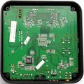
Device disassembly
This casing is trivially disassembled by removing 4 Philips screws on the bottom.
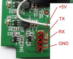
Locating the UART
The UART pads are clearly marked on the top of the board. You can solder in a 2.54mm pitch header as shown in the picture, or you can solder on wires directly. For more information read our UART howto.
