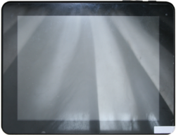
INet 3W
| INet 3W | |
|---|---|
 | |
| Manufacturer | iNet Tek |
| Dimensions | 243mm x 187mm x 10mm |
| Release Date | October 2013 |
| Specifications | |
| SoC | A10 @ 1Ghz |
| DRAM | 1GiB @ 408MHz |
| NAND | 8GB |
| Power | DC 5V @ 2A, 5000mAh 3.7V Li-Ion battery |
| Features | |
| LCD | 1024x768 (9.7" 4:3) |
| Touchscreen | 10-finger capacitive (Focaltech FT5406EE8) |
| Video | HDMI (Type C - mini) |
| Audio | 3.5mm headphone plug, HDMI, internal speaker, internal microphone |
| Network | WiFi 802.11 b/g/n (iNet i10) |
| Storage | µSD |
| USB | 1 USB2.0 Host, 1 USB2.0 OTG |
| Camera | 0.3MP (640x480) front (Galaxycore GC0308), 2MP 1600x1200) rear (Galaxy Core GT2005) |
| Other | Accelerometer (Bosch BMA250), Bluetooth (Broadcom BCM40183), WCDMA modem (HTF HWM630), SIM card port |
| Headers | UART |
The iNet 3W tablet comes with a WCDMA modem and a SIM card port.
Identification
The PCB has the following silkscreened on it:
INET-3W-REV03
Zng-gc 2013-03-26
In Android, under Settings->About Tablet, you will find:
- Model Number: M9701TW
- Build Number: 03W1-P1-H2-H02-CY40.20121230
Sunxi support
Current status
The device is supported and maintained in mainline U-Boot. There is no mainstream kernel support at this point. Linux (sunxi-3.4 branch) boots on the device, but most features are untested.
Manual build
- For building U-Boot, use the iNet_3W target.
- The .fex file can be found in sunxi-boards as inet_3w.fex
Everything else is the same as the manual build howto.
Mainline U-Boot
For building mainline U-Boot, use the iNet_3W target.
Tips, Tricks, Caveats
FEL mode
Sending '2' over UART at boot triggers FEL mode from boot1.
USB storage mode
Sending '1' over UART at boot triggers an USB storage mode that exposes the nanda partition as well as the Android external storage.
Reset button
The reset button (on the PCB) reboots the device.
Adding a serial port (voids warranty)
Device disassembly
In order to open the device, there are two Phillips screws to remove from the side with the connectors. The pins from the white part are easy to pop but it is advised to use a a plastic tool, starting from the side with the connectors. The front panel is very fragile and pressuring the screen to pop open the pins can easily end up in breaking the touch screen panel.
Locating the UART
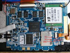
The UART pads are exposed in a very visible way on the PCB, close to the touchscreen connector. The pads are clearly labeled on the PCB: GND, Rx, Tx. Connectors can easily be soldered according to the UART howto.
Pictures
Also known as
- AM-975


