Hyundai A7
| Hyundai A7 | |
|---|---|
 | |
| Manufacturer | Hyundai Digital (defunct) |
| Dimensions | 193mm x 118mm x 13mm |
| Release Date | January 2012 |
| Website | Product Page(defunct) |
| Specifications | |
| SoC | A10 @ 1Ghz |
| DRAM | 512MiB DDR3 @360MHz (H5TQ1G83TFR-H9C) |
| NAND | 8GB |
| Power | USB, 3000mAh 3.7V Li-Ion battery |
| Features | |
| LCD | 800x480 (7" 16:9) |
| Touchscreen | 5-finger capacitive/resistive (Goodix GT801) |
| Video | HDMI (Type C - mini) |
| Audio | 3.5mm headphone plug, HDMI, internal speaker, internal microphone |
| Network | WiFi 802.11 b/g/n (Realtek RTL8188CUS) |
| Storage | µSD |
| USB | 1 USB2.0 OTG |
| Camera | 0.3MP (640x480) front-facing |
| Other | Accelerometer (Manufacturer device FIXME) |
| Headers | UART, JTAG |
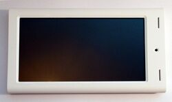
The Hyundai A7 was a cheap A10 based tablet, with a very distinctive case. It was available in both black and white.
Identification
The Hyundai A7 has a pretty distinctive case, and handily has "HYUNDAI" and "A7" written on the back.
In android, under Settings->About Tablet, you will find:
- Model Number: M723-GDX
- Kernel Version: 3.0.8+ worldchip@worldchip-gcb #53
- Build Number: crane_m723gdx-eng 4.0.1 ITL41D eng worldchip.20120114.165124 test-keysDEVICE
Sunxi support
Supported.
Current status
Images
HW-Pack
BSP
Manual build
- For building u-boot, use the "Hyundai_A7" target.
- The .fex file can be found in sunxi-boards as hyundai_a7.fex
Everything else is the same as the manual build howto.
Tips, Tricks, Caveats
FEL mode
To trigger FEL mode, there is a UBOOT button under the pin-hole left of the HDMI connector.
Adding a serial port (voids warranty)
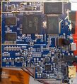
Device disassembly
Start at the connector side. The plate with the connectors is part of the front cover, as is the other side of the cover. Stick your plastic tool into the microSD slot and gently push the connector plate out. There are three clips here, one in the middle and 2 on each side.
Once you have loosened the 3 connector side clips, turn your attention to the back long sides of the device. Here the back cover needs to be pushed out (so different than the connector side). There are 5 clips here.
If this is the first time that you open the device, then the battery is taped to the back. So don't worry if your back cover doesn't let go immediately.
Now that the clips on the back cover are loose, turn your attention to the non-connector short edge. Here, like with the connector side, there are 3 clips, and the front cover needs to be pushed out.
Once you are certain that all the clips have released, you can gently pry the back cover away from the double sided tape on the battery.
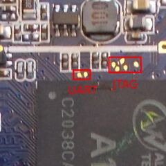
Locating the UART
There are obvious RX/TX pads left of the SoC, but those are very very small and will take a lot of skill to solder. For more information check our UART howto.


