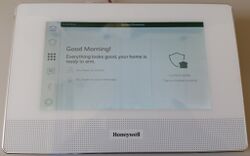
Honeywell VDP7
| Honeywell VDP7 | |
|---|---|
 | |
| Manufacturer | Honeywell |
| Dimensions | 217mm x 144mm x 17mm |
| Release Date | 2018 |
| Website | not available] |
| Specifications | |
| SoC | A64 @ 1.2Ghz |
| DRAM | 1GiB DDR3 @ 672MHz |
| NAND | None |
| Power | DC 12V @ 2A |
| Features | |
| LCD | 154mm x 86mm (7" 1024:600Pixel) |
| Touchscreen | 5-finger capacitive Touchscreen (GT911) |
| Video | None |
| Audio | internal speaker, internal microphone |
| Network | WiFi 802.11 b/g/n (Realtek RTL8189ES), 10/100Mbps Ethernet (ASIX AX88772C) |
| Storage | µSD, eMMC |
| USB | USB2.0 Host (Connected to AX88772C), USB2.0 OTG (Pin-Header J4) |
| Camera | None |
| Other | None |
| Headers | UART, USB-OTG, LVDS-LCD, MIPI-LCD, Touch, Camera, ... |
Identification
On the back of the device, the following is printed:
Honeywell
Model: VDP7-KA-W
7" IPVDP monitor, KA channel.White
The PCB has the following silkscreened on it:
TC-HONEYWELL-A64-JK-V15
2017-12-08
TC3287
In GUI, under Settings->About, you will find:
- Device Name: Tuna
Sunxi support
Current status
The device is currently not supported by default by uboot or the Linux kernel
Manual build
You can build things for yourself by following our Manual build howto and by choosing from the configurations available below.
U-Boot
Sunxi/Legacy U-Boot
Use the MANUFACTURER_DEVICE build target.
Mainline U-Boot
Use the MANUFACTURER_DEVICE build target.
Use the following config with minimal own created A64 dts-files:
CONFIG_ARM=y
CONFIG_ARCH_SUNXI=y
CONFIG_SPL=y
CONFIG_MACH_SUN50I=y
CONFIG_RESERVE_ALLWINNER_BOOT0_HEADER=y
CONFIG_DRAM_ODT_EN=y
CONFIG_MMC0_CD_PIN=""
CONFIG_MMC_SUNXI_SLOT_EXTRA=2
CONFIG_SPL_SPI_SUNXI=y
CONFIG_DEFAULT_DEVICE_TREE="sun50i-a64-vdp7" # Currently missing
CONFIG_DM_REGULATOR=y
CONFIG_DM_REGULATOR_FIXED=y
CONFIG_DM_PWM=y
CONFIG_PWM_SUNXI=y
# CONFIG_SYS_MALLOC_CLEAR_ON_INIT is not set
# CONFIG_CMD_FLASH is not set
# CONFIG_SPL_DOS_PARTITION is not set
# CONFIG_SPL_EFI_PARTITION is not set
CONFIG_USB_EHCI_HCD=y
CONFIG_SYS_USB_EVENT_POLL_VIA_INT_QUEUE=y
Linux Kernel
Sunxi/Legacy Kernel
Use the MANUFACTURER_DEVICE.fex file.
Mainline kernel
Use the FAMILY-CHIP-DEVICE.dtb device-tree binary.
Tips, Tricks, Caveats
FEL mode
The Emergency button on the right side triggers the FEL mode. The corresponding USB OTG is available on the extension board connector J4 and has the following pin out:
- VBUS
- DM
- DP
- USB-ID
- GND
LVDS-Display
Is connected over LVDS pins PD12-PD21 on LCD2 connector.
Device disassembly
Remove the back 4 screws. There is a hole on the bottom back housing were a screw driver could be placed to open it.
Power Supply (J3)
The assembled connector J3 in the near of the network jack is for the 12V power supply and has the following pin out:
- +12V
- GND
Locating the UART0 (J6)
There is a not assembled connector J6 marked on the right extension board which is connected to UART0 and has the following pin out:
- GND
- TX
- VCC
- RX
Locating the UART3/4 (CON2)
The connector CON2 has 2 RS485 UARTs connected.
- DBEL
- GND
- UART3-A
- UART3-B
- UART4-A
- UART4-B
Locating the USB-OTG (J4)
There is a not assembled connector J4 marked on the right extension board which is connected to USB0 and has the following pin out:
- VBUS
- DM
- DP
- ID
- GND
Pictures
Also known as
- VDP7-KA-W
- VDP7-KA-B
- VDP7-PRO-W
- VDP7-PRO-B


