FriendlyARM NanoPi A64
| FriendlyARM NanoPi A64 | |
|---|---|
 | |
| Manufacturer | FriendlyARM |
| Dimensions | 64mm x 60mm |
| Release Date | Dec 2016 |
| Website | NanoPi A64 Product Page |
| Specifications | |
| SoC | A64 @ up to 1152 Mhz |
| DRAM | 1GiB DDR3 @ xxxMHz ( Samsung K4B4G1646D-BCK0 * 2) |
| NAND | none |
| Power | DC 5V @ 2A via microUSB or pin headers |
| Features | |
| Video | HDMI (Type A - full), MIPI DSI |
| Audio | 3.5mm headphone/microphone plug, HDMI, SPDIF |
| Network | WiFi 802.11 b/g/n (RTL8189ETV), 10/100/1000Mbps Ethernet (Realtek RTL8211E) |
| Storage | µSD |
| USB | 2 x USB 2.0 (shared, internal hub), 1 USB 2.0 OTG |
| Other | IR Receiver |
| Headers | RPi compatible GPIO, UART Header, I2S Header (not populated), MIPI DSI, DVP Camera |
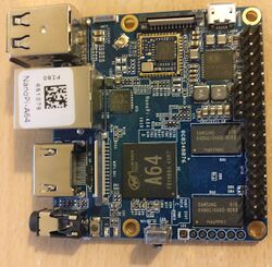
NanoPi A64 is A64 based development board produced by FriendlyARM. It comes with onboard gigabit Ethernet, 802.11 b/g/n WiFi, HDMI, and two USB A ports.
Identification
There is a label on top of the Ethernet port with a QR code and "NanoPi-A64" written on it. Also on the SoC there is a quite prominent "A64" print.
On the back of the device, the following is printed:
FRIENDLYARM
The PCB has the following silkscreened on it:
NanoPi-A64
Sunxi support
Current status
From the software point of view this device is similar to the Pine64 (similar DRAM, same Ethernet and PMIC), so basic support should work with some Pine64 image if PMIC configuration is identical (at least according to this review Pine64 images don't even boot).
BSP
FriendlyARM provides an adopted BSP on Github
Manual build
You can build things for yourself by following our Manual build howto and by choosing from the configurations available below.
U-Boot
Sunxi/Legacy U-Boot
Mainline U-Boot
Use the nanopi_a64_defconfig build target (supported since v2017.09).
Linux Kernel
Sunxi/Legacy Kernel
Mainline kernel
Use the sun50i-a64-nanopi-a64.dtb device-tree binary.
Tips, Tricks, Caveats
FEL mode
There is no FEL button on this board. Booting without an SD card automagically enters FEL mode.
USB OTG
A64's USB OTG port is exposed as Type A receptacle and the Micro USB jack is for powering only (exactly identical with Pine64).
Powering the board
A battery connector has been saved so the only way to power the board is with 5V through GPIO headers (either 40 pin or the 4 pin debug header) or the Micro USB jack. In case you use the latter please keep in mind that a lot of stability/boot problems are related to Micro USB being the wrong choice for DC-IN. At least the Micro USB cable FriendlyARM ships with the device is of good quality (low resistance).
ESD & over-current protections
Based on the schematic Rev 1610 (December 15, 2016) the board incorporates the following protections:
| Protections
x - no protection, ESD - Electrostatic Discharge, OC - Over-current |
Comments | |||
|---|---|---|---|---|
| 1 | USB micro (power) | x | x | Power supply bypass. |
| 2 | Micro SD | x | x | |
| 4 | Camera | x | x | |
| 5 | Display | x | x | |
| 6 | Dual USB | ESD | x | Power supply bypass. |
| 7 | HDMI | ESD | x | |
| 8 | Ethernet | x | N/A | Over-current protection is not applicable. |
| 9 | GPIO | x | x | Only UART2 & UART3 have ESD protection. |
| 10 | Debug UART | ESD | OC | Current is limited by using resistors. |
| 11 | Audio jack | ESD | N/A | Output current is internally limited by SoC. |
Serial port / UART
The board exposes 2 UART ports trough the GPIO header and the UART0 port on a separate 4 pin header
UART2 uses pins 11 (TX), 22 (RX) and UART3 uses pins 8 (TX), 10 (RX).
All of the UARTs use 3.3V voltage levels. Look at our UART howto for further instructions.
Locating the UART
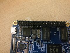
Below the GPIO there is a separate 4 pin header with "DBG_UART" silkscreened next to it, in the bottom of the board the labels "RX", "TX", "5V", "GND" can be found next to the corresponding pins.
Pictures
See also
- The NanoPi wiki shows how to build the BSP that can be found in Manufacturer images: http://wiki.friendlyarm.com/wiki/index.php/NanoPi_A64
- The NanoPi A64 product page lists some useful accessories (eg. the necessary heatsink when you want to continually run heavy loads on the board): http://www.friendlyarm.com/index.php?route=product/product&product_id=159


