Anichips PhoenixA20/Headers
The Anichips PhoenixA20 board has four 2.00mm pitch headers. These are labelled UART, digital, analogue and LCD. The information here has been pulled from an inspection of the board, the PhoenixA20 schematics and the Allwinner A20 User Manual.
A number of pins are controlled through the Allwinner A20 port controller. These pins are shown as (Pxn) in the diagrams below, where x is the port identifier (A through to S) and n is the pin number. By modifying a FEX file for a sunxi 3.4 Linux kernel or a DTS file for a mainline Linux kernel the use of the port can be modified. For example the LCD pins can be re-purposed as a LVDS video interface. If port controlled pins are unused they can be set up as general purpose input/output (GPIO), with the LCD connector this gives a potential 28 GPIO pins. The Allwinner A20 User Manual provides mappings between pin and purpose.
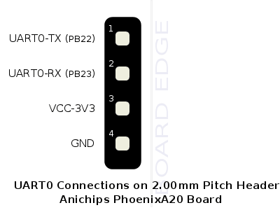
UART Header
This header provides access to UART0 and can be used for debugging.
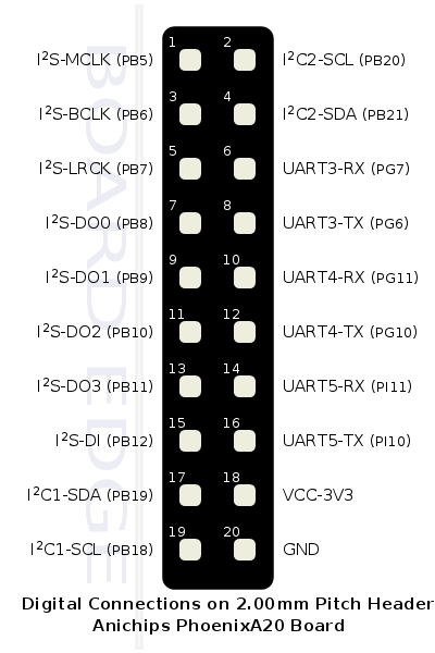
Digital Header
The digital header mainly provides three additional UART interfaces and two I2C interfaces.
On the board pins are also labelled for Inter-IC Sound (I2S), but the schematics show these pins are used to carry Bluetooth PCM audio between the AP6210 and A20 audio system. One of the I2S labelled pins (PB9) is used as a USB power switch. This leaves two pins (PB10 and PB11) unused and these could be configured as GPIO for a 1-wire interface. For anyone interested in I2S this post, CUBIEBOARD FOR AUDIO?, that discusses the CubieTruck may be a starting point.
The UART interfaces are numbered 3,4 and 5 and this corresponds to the numbers used on the A20 SOC. UART0 is exposed on a separate header shown above, UART1 is not available as the pins are used for the Ethernet MAC controller and UART2 is connected to the Bluetooth chip of the AP6210. The numbers exposed in the Linux user space will be different because UART1 is not available.
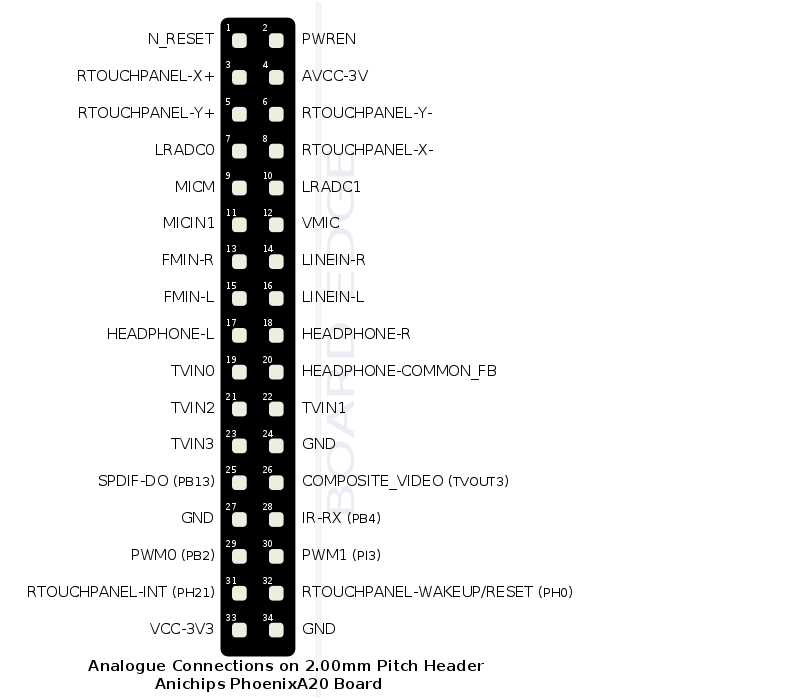
Analogue Header
The analogue header mainly provides audio, human input and video interfaces. The header also has the power enable and reset pins for the power management unit.
For audio there are pins for:
- Mono microphone
- Stereo line level input
- Stereo auxiliary input (marked as from an auxiliary FM tuner, there is no FM tuner on the A20 SOC)
- Stereo headphones
- SPDIF output
For human input there are pins for:
- Resistive touchpanel
- Two low resolution ADCs (6bit, 0-2V) usually used for buttons
- Infra-red receiver, confusingly the schematic shows the pin wired to IR-RX(PB4) but labels the pin on the connector as IR-OUT.
For video there are pins for:
- Composite video out
- TV in, these are undocumented for Allwinner SOCs so are effectively useless
There are also two Pulse Width Modulation pins (PWM) that could be used for controlling LED brightness or a stepper motor.
Very few of the pins are part of the port controller so most cannot be re-purposed as GPIO pins.
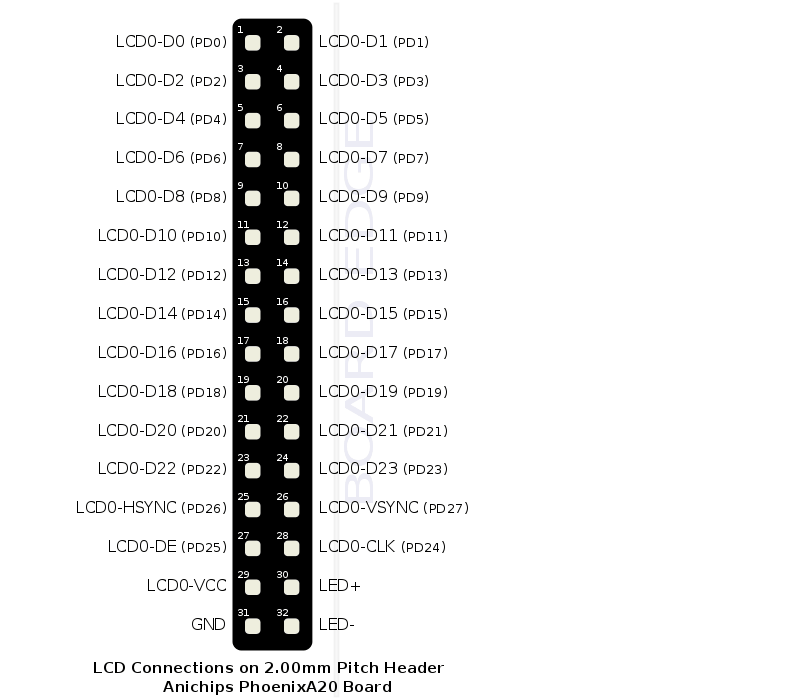
LCD Header
The LCD header could be re-purposed as a 28 pin GPIO header. The A20 User Manual also shows the pins could be re-purposed for LVDS video connector.


