Anichips PhoenixA20
| Anichips PhoenixA20 | |
|---|---|
 | |
| Manufacturer | Anichips Technology |
| Dimensions | 100mm x 72mm (Pico-ITX) |
| Release Date | November 2013 |
| Website | News/Product Page |
| Specifications | |
| SoC | A20 @ 1GHz |
| DRAM | 1GiB DDR3 @ xxxMHz |
| NAND | 4GB |
| Power | DC 5V @ 2A |
| Features | |
| Video | HDMI, VGA |
| Audio | HDMI |
| Network | WiFi 802.11 b/g/n (Ampak AP6210), 10/100Mbps Ethernet (Realtek RTL8201CP) |
| Storage | µSD , SATA |
| USB | 2 USB2.0 Host |
| Other | Bluetooth (Ampak AP6210), EEPROM |
| Headers | UART, LCD, Camera, 2 expansion connectors. |
This page needs to be properly filled according to the New Device Howto and the New Device Page guide.
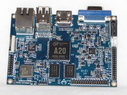
The phoenixA20 is a Pico-ITX sized development board.
Identification
Near the Wifi/Bluetooth module, opposite from the Ethernet connector, the PCB reads:
Phoenix V2.0 2013-10-24
Designed by EASITEK&ANICHIPS
Sunxi support
Current status
No patches have been submitted for inclusion in the sunxi repositories.
Images
HW-Pack
BSP
Manual build
- For building u-boot, use the "MANUFACTURER_DEVICE" target.
- The .fex file can be found in sunxi-boards as MANUFACTURER_DEVICE.fex
Everything else is the same as the manual build howto.
Tips, Tricks, Caveats
FEL mode
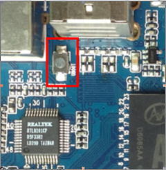
The U-boot button triggers FEL mode.
ADB
To use ADB, you need to connect the board ONLY via the USB cable and don't connect the power-cable.
Ethernet
The Allwinner A20 provides two Ethernet MAC controllers: EMAC and GMAC. The PhoenixA20 board uses the EMAC controller.
Headers
There are four 2.00mm pitch headers on the board. These are labelled UART, digital, analogue and LCD. The digital header mainly provides three additional UART interfaces, two I2C interfaces and two spare pins that could be used as GPIOs for two 1-wire interfaces. There is also a possibility of using it for Inter-IC Sound (I2S). The analogue header provides audio, human input, video and PWM interfaces and the power enable and reset pins. The LCD header could be re-purposed as a 28 pin GPIO header. For more details see the PhoenixA20 Headers page.
Improved WIFI reception
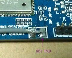
To improve Wifi reception you can solder a wire to the board of about 10cm long
VGA
Like with most devices based on Allwinners reference platform, no DDC is available, and the monitors capabilities cannot be detected.
Adding a serial port
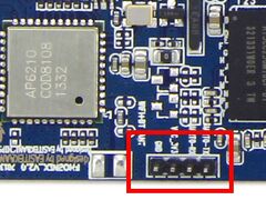
There is a clearly marked 2.00mm pitch header for UART debugging on the board. A 2.00mm pitch connector to 2.54mm pitch header cable is also supplied with the board. Just connect the leads according to the UART howto
Pictures
Also Known as
This type of device has no rebadgers.


