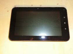
Along rt713
| Along rt713 | |
|---|---|
 | |
| Manufacturer | Along |
| Dimensions | 196mm x 120mm x 10mm |
| Release Date | May 2012 |
| Website | Rebadger Product Page |
| Specifications | |
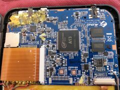
| SoC | A13 @ 1Ghz |
| DRAM | 512MiB DDR3 @ 408MHz |
| NAND | 4GB |
| Power | DC 5V @ 2.5A, 2800mAh 3.7V Li-Ion battery |
| Features | |
| LCD | 800x480 (7" 16:9) |
| Touchscreen | 5-finger capacitive/resistive (FocalTech ft5x FIXME) |
| Audio | 3.5mm headphone plug, internal speaker, internal microphone |
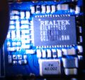
| Network | WiFi 802.11 b/g/n (Realtek RTL8188EUS) |
| Storage | µSD |
| USB | 1 USB2.0 OTG |
| Camera | 0.3MP (640x480) front |
| Other | Accelerometer (Freescale MMA7660) |
| Headers | UART |
This page needs to be properly filled according to the New Device Howto and the New Device Page guide.
This device uses the pretty popular MID formfactor, like the A710 and A721, but instead comes with an A13 based mainboard.
Identification
In android, under Settings->About Tablet, you will find:
- Model Number: eXagerate XZPAD700
- Build Number: exg_eb-ita 4.0.4 HML 20121122
Sunxi support
Current status
Supported but there are some issues with the touchscreen driver.
Images
HW-Pack
BSP
Manual build
- For building u-boot, use the "xzpad700" target.
- The .fex file can be found in sunxi-boards as xzpad700.fex
Everything else is the same as the manual build howto.
Tips, Tricks, Caveats
FEL mode
The VOL+ button triggers FEL mode.
Touchscreen
As of 3.4.103 the ft5x GPL touchscreen driver seems to work right. Save a look at the Touchscreen page for more details on inverting or exchanging axix.
CSI Connector Pin-Out
On board version 2.0 2012.10.01 this is the pin-out of the CSI connector
| CSI Connector PIN | A13 PIN | A13 PIN NAME |
|---|---|---|
| 1 | ||
| 2 | GND | GND |
| 3 | ||
| 4 | ||
| 5 | ||
| 6 | ||
| 7 | 117 | PE3 |
| 8 | ||
| 9 | 116 | PE2 |
| 10 | ||
| 11 | ||
| 12 | 125 | PE11 |
| 13 | 115 | PE1 |
| 14 | 124 | PE10 |
| 15 | GND | GND |
| 16 | 123 | PE9 |
| 17 | 114 | PE0 |
| 18 | 122 | PE8 |
| 19 | 118 | PE4 |
| 20 | 121 | PE7 |
| 21 | 119 | PE5 |
| 22 | 120 | PE6 |
| 23 | GND | GND |
| 24 | GND | GND |
The ones left out are not directly connected to the A13 but may be connected to power, reference voltages or other stuff that could damage the A13 if connected to the I/O pins.
Adding a serial port (voids warranty)
Device disassembly
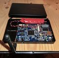
There are 4 screws which need to be removed first. 2 on the connector side and 2 on the opposite side. Use your plastic tool to carefully release all the clips by pushing the back cover inwards. Go over all 4 sides. When opening up the device, be careful as the speaker is attached to the rear cover.
Locating the UART
Although the fex file has evidence that at some time pins PG3 (pin 152) and PG4 *pin 151) were used for an UART port, this may date back to prototyping and may have been physically removed from the production units as I was unable to track down any test pads physically connected to these pins. In the process of attempting to track these test pads I blew a USB serial adapter cable because of the high voltages (up to 24V) present on some test pads so be warned that if you want to double check whether I missed something you should keep clear from the following test pads: TP36, TP73, TP74, TP76.
If you really need to have a serial console to this device while still using the uSD this is how I suggest you you go about it:
- take off the CSI camera sensor
- disable csi from the fex
- remap uart to use pins PE11 (RX) and PE10 (TX)
- connect the uart to the CSI flext cale connector pins 12 (RX), 14 (TX) and any of 2 15 23 or 24 as GND
Where TX and RX are referred to the rt713 side and the CSI connector pin 24 is the closest to the pcb edge (Vol +).
Have a look at the UART howto for more details on hooking op a serial console.
I've checked and I was able to get the serial console to partially work by using this fex configuration: rt713_remap_csi2uart.fex. I was able to receive on the PC output sent by the A13 but I was unable to send data to A13. Can anybody double check if I did things right with the fex ? I've checked that PE11 is actually connected to pin 12 on the CSI connector by configuring that pin for GPIO and testing voltage with a multimeter while switching it at it worked right. Not sure if I did something else wrong or if my unit is damaged.
If you actually solder the uart to a spare flect cable, open up the device without leaving evidence of you doing that and keep the original script.bin I think it would not void your warranty!
Pictures
Further pictures:
Also Known as
See also
- Slackware on the XZPAD700: This article can be used to get Slackware on most Axx devices.
- A710: Same housing, but different board with an A10.
- A721: Same housing, but another different board with an A10.


