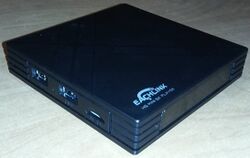
Eachlink H6 Mini
| Eachlink H6 Mini | |
|---|---|
 | |
| Manufacturer | Eachlink (?) |
| Dimensions | 96mm x 96mm x 20mm |
| Release Date | September 2018 |
| Website | (none?) |
| Specifications | |
| SoC | H6 @ 1.3 Ghz |
| DRAM | 3GiB DDR3 @ 840(?) MHz |
| NAND | 32GB eMMC |
| Power | DC 5V @ 2A, microUSB |
| Features | |
| Video | HDMI (Type A full) |
| Audio | 3.5mm AV plug, HDMI, SPDIF |
| Network | WiFi 802.11 b/g/n (Realtek 8723BS), 10/100Mbps Ethernet (embedded AC200) |
| Storage | µSD, eMMC |
| USB | 1 X USB2.0 Host, 1 X USB3.0 Host |
| Other | IRDA receiver, 7-segment display |
| Headers | UART pads |
This page needs to be properly filled according to the New Device Howto and the New Device Page guide.
Inexpensive TV box with the H6 SoC and some decent specifications (3GiB RAM, 32GiB eMMC), but missing GBit Ethernet.
Identification
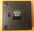
On the back of the device, the following is printed:
H6 MINI PLAYER
HOME MEDIA CENTER
DESIGNED BY HONG KONG
INPUT: DC 5V / 2A
MADE IN CHINA
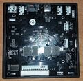
The PCB has the following silkscreened on it:
H6-mini_H6_V1.1 2018-09-11
in a later version
H6-mini_H6_V1.2 2018-09-15
Sunxi support
Current status
WIP. Boots mainline Linux headless (with serial console soldered as shown below), with SD card, eMMC and USB 2.0 working.
Images
Manual build
You can build things for yourself by following our Manual build howto and by choosing from the configurations available below.
U-Boot
Mainline U-Boot
Support is work in progress. Patches have been posted to the mailing list, a repository with those patches is available.
Linux Kernel
Mainline kernel
Any recent kernel with H6 support should work. No mainline .dts yet, use the .dtb as provided by U-Boot, by using $fdtcontroladdr when specifying the DTB address.
Tips, Tricks, Caveats
Despite being a TV box shipped with Android and the Play Store plus other sensitive apps, the box is completely open. It boots normal eGON images (as created by U-Boot) or boots happily into FEL mode with the FEL button pressed. When booting the shipped Android system, you are greeting with a prompt on the serial line. If you have the RX line fix in place, you can explore the system. A dauntless "su" will give you root privileges for full system access.
- The box does not seem to come with the usual AXP 805 PMIC (typically bundled with the H6). There is an IC which looks like a PMIC, judging by the coils and the many SMD components around it. However it is much smaller than the AXP and has a rather cryptic label "A8038 8099330k". The BSP log features "probe axp is dummy" and "no pmu exist".
- The LED 7-segment display is controlled by an I2C controlled chip called FD655 from the Chinese company FDHISI (TODO: find I2C bus number, I2C address and required power lines for the display. Google turns up a Chinese datasheet, also there is some driver code on Github).
- There are eight(!) DRAM chips, four from Samsung (K4B2G0446D) and four from Micron (D9PQL). On the v1.2 board, there are four K4B2G0446Q and four K4B2G0446C all from Samsung. It needs to be worked out whether this is to give the rather odd 3GiB or there are actually 4GiB, with the last GiB not usable.
To get a root-shell in the shipped Android system without hardware modification (uart and a serial line) via tcp instead, you can install temporarily and start com.jaja.remoteadb. Connect from a external PC with an installed adb
$ adb connect <ip of your box>
$ adb shell
petrel-p1:/ #
To start adb permanently listening (after reboot) to network port 5555 you set
petrel-p1:/ # setprop persist.adb.tcp.port 5555
You can remove com.jaja.remoteadb, after adb is permanently listening to port 5555
petrel-p1:/ # pm uninstall com.jaja.remoteadb
FEL mode
There is a small hole between the two USB ports, the button behind it triggers FEL mode when held down while resetting or powering up. On the PCB there is written "UBOOT" near this button. The USB 2.0 port will act as the OTG device, you need a USB-A <-> USB-A cable for FEL mode (same as the Pine64).
$ ./sunxi-fel version
AWUSBFEX soc=00001728(H6) 00000001 ver=0001 44 08 scratchpad=00007e00 00000000 00000000
If you copy the original spl from internal eMMC to an empty sd-mmc between 0x2000 and 0xa000 the box with this sd-mmc inserted will fall into FEL mode automatically:
petrel-p1:/ # dd if=/dev/block/mmcblk0 of=/dev/block/mmcblk1 bs=8k seek=1 skip=1 count=4
petrel-p1:/ # reboot
You will find the original spl in the ota-update zip as file named boot0_sdcard.fex with size 32768.
Adding a serial port (might void warranty?)
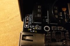
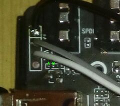
There are clearly labelled UART pads on the PCB, please refer to the UART howto for more details on using a serial port. There is some space near the microUSB power supply socket to drill a small hole and lead the three needed cables through.
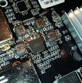
The RX pin doesn't work out of the box, as there is a FET missing on the PCB. Normally this FET gates the RX line when the device is off, preventing it from leaking power into the system and allowing a proper shutdown and reboot. However this FET is not populated, so the RX line is not working initially: You can't type anything, but see all messages. To fix this either bridge the pins labelled "S" and "D" in the picture to the right, or solder a proper FET to the SOT23 footprint.
On the v1.2 the TX pin doesn't work out of the box, too, as there is a resistor missing on the PCB. You can put a 10kΩ resistor in between the pins labeled "A" and "B".
Device disassembly
To open the box, turn it upside down, gently slide a plastic tool or a knife in the small gap around all edges of the box to eventually lift the bottom plate. There is no need to remove the rubber feet. Then unscrew the four screws securing the PCB. To remove the PCB, first lift the side with the 7 segment display up (use a knife or similar tool), then gently pull the PCB out. This is needed because the backside connectors are somewhat locked into the case.
Locating the UART
The UART pins are located in the upper left corner on the top of the PCB, near the SPDIF connector. They are the usual 3.3V GND/TX/RX/VCC pin, clearly labelled as such. As usual, the VCC should not be needed.
Pictures
See also
Add some nice to have links here. This includes related devices, and external links.
Manufacturer images
Optional. Add non-sunxi images in this section.
