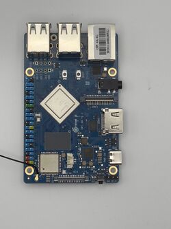
Xunlong Orange Pi 4A
| Xunlong Orange Pi 4A | |
|---|---|
 | |
| Manufacturer | OrangePi |
| Dimensions | 89mm x 56mm x 1.6mm |
| Release Date | November 2024 |
| Website | Device Product Page |
| Specifications | |
| SoC | T527 @ 1.8 Ghz |
| DRAM | 2GiB/4GiB LPDDR4/4X |
| NAND | eMMC connector |
| Power | DC 5V @ 5A via USB-C connector |
| Features | |
| Video | HDMI 2.0a (Type A full), 4-lane MIPI-DSI, eDP1.3 |
| Audio | 3.5mm audio in/out plug |
| Network | WiFi 802.11 b/g/n/ac (AP6256), 10/100/1000Mbps Ethernet (Motorcomm YT8531C) |
| Storage | µSD, eMMC connector, 128Mbit SPI flash (XMC XM25QU128), M.2 M Key for 2280 SSD |
| USB | 3x USB2.0 Host, 1x USB2.0 OTG, 1x USB 2.0 HOST via 4-pin expansion |
| Camera | 1x 2-lane MIPI-CSI, 1x 4-lane MIPI-CSI camera interface |
| Headers | 40pin GPIO, 3pin debug serial port, 2pin RTC battery, 4pin ADC |
This page needs to be properly filled according to the New Device Howto and the New Device Page guide.
Identification
The PCB has the following silkscreened on it:
Orange Pi Logo
OPI 4A V1.1
Sunxi support
Current status
Not Supported
Images
Optional. Add MANUFACTURER DEVICE specific sunxi ROM images here. E.g. a livesuit image or some other linux image which uses linux-sunxi code. Do not put non-sunxi images here, they should live under See also. If no sunxi based images are available, this section can be removed.
HW-Pack
Optional. Add MANUFACTURER DEVICE sunxi HW-pack specifics here. When empty, this section can be removed.
BSP
Optional. Add MANUFACTURER DEVICE sunxi BSP specifics here. When empty, this section can be removed.
Manual build
You can build things for yourself by following our Manual build howto and by choosing from the configurations available below.
U-Boot
Sunxi/Legacy U-Boot
Only useful for A10/A10s/A13 and A20 based devices. Remove this section otherwise.
Use the MANUFACTURER_DEVICE build target.
Mainline U-Boot
Use the MANUFACTURER_DEVICE build target.
Linux Kernel
Sunxi/Legacy Kernel
Only useful for A10/A10s/A13 and A20 based devices. Remove this section otherwise.
Use the MANUFACTURER_DEVICE.fex file.
Mainline kernel
Use the FAMILY-CHIP-DEVICE.dtb device-tree binary.
Expansion ports
The OrangePi 4A has a 40-pin, 0.1" populated connector with several low-speed interfaces.
The primary function follows loosely the Raspberry Pi pin assignment, but pinmuxing gives access to more interfaces (not all at the same time).
| GPIO number | Function4 | Function3 | Function2 | Function1 | PIN# | PIN# | Function1 | Function2 | Function3 | Function4 | GPIO number | |
|---|---|---|---|---|---|---|---|---|---|---|---|---|
| +3.3V | 1 | 2 | +5.0V | |||||||||
| 257 | UART4-TX | TWI4-SDA | PI1 | 3 | 4 | +5.0V | ||||||
| 256 | PWM0-1 | UART4-RX | TWI4-SCK | PI0 | 5 | 6 | GND | |||||
| 36 | TWI1-SCK | PWM0-8 | PB4 | 7 | 8 | PB13 | UART7-TX | PWM0-4 | 45 | |||
| GND | 9 | 10 | PB14 | UART7-RX | PWM0-5 | 46 | ||||||
| 32 | SPI2-CSO | PWM0-6 | UART2-TX | PB0 | 11 | 12 | PB5 | PWM0-9 | TSI1-SDA | 37 | ||
| 33 | SPI2-CLK | PWM0-7 | UART2-RX | PB1 | 13 | 14 | GND | |||||
| 34 | SPI2-MOSI | PB2 | 15 | 16 | PI13 | PWM0-14 | 269 | |||||
| +3.3V | 17 | 18 | PI14 | PWM0-15 | 270 | |||||||
| 261 | SPI1-MOSI | PI4 | 19 | 20 | GND | |||||||
| 260 | SPI1-MISO | PI5 | 21 | 22 | PI6 | UART6-TX | 258 | |||||
| 259 | UART5-RX | SPI1-CLK | PI3 | 23 | 24 | PI2 | SPI1_CS0 | UART5-TX | 262 | |||
| GND | 25 | 26 | PI7 | UART6-RX | 263 | |||||||
| 265 | TWI5-SDA | PI9 | 27 | 28 | PI8 | TWI5-SCK | 264 | |||||
| 35 | SPI2-MISO | PB3 | 29 | 30 | GND | |||||||
| 43 | PWM0-2 | PB11 | 31 | 32 | PI11 | PWM0-12 | UART3-TX | 267 | ||||
| 268 | UART3-RX | PWM0-13 | PI12 | 33 | 34 | GND | ||||||
| 38 | PWM0-10 | PB6 | 35 | 36 | PI10 | 266 | ||||||
| 44 | PB12 | 37 | 38 | PB7 | PWM0-11 | 39 | ||||||
| GND | 39 | 40 | PB8 | 40 |
Tips, Tricks, Caveats
Add MANUFACTURER DEVICE specific tips, tricks, Caveats and nice to have changes here.
FEL mode
The something button triggers FEL mode.
SPI booting
The board contains a 16MB SPI NOR flash chip, and the SoC can boot firmware from there.
Using serial port
Like with other Orange Pi boards, UART uses 3.3V signalling and is 5V tolerant so you can use any of the usual USB-UART dongles. UART pin header is easily accessible.
Locating the UART
The 3 UART pins are located adjacent to the power key and are clearly marked. You can use this serial port to log in or debug the system with a baud rate of 115200, 8 data bits, 1 stop bit, no parity. Just attach some leads according to our UART Howto.
Pictures
Schematic
- Schematics 1.1: File:OPI 4A V1 1 SCH.pdf
See also
Add some nice to have links here. This includes related devices, and external links.
Manufacturer images
- Official Ubuntu image, based on the BSP kernel.
- Official Debian image, based on the BSP kernel.
- Official Android image, based on the BSP kernel.

