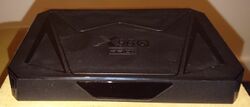
X96QPro+
| X96QPro+ | |
|---|---|
 | |
| Manufacturer | Manufacturer |
| Dimensions | 140mm x 90mm x 20mm |
| Release Date | August 2024 |
| Website | Device Product Page |
| Specifications | |
| SoC | H728 @ 1.8Ghz |
| DRAM | 2GiB/4GiB DDR3L @ 792MHz (8*Micron MT41K1G4RH-107:E) |
| NAND | 16/32/64 GB eMMC |
| Power | DC 5V @ 2A |
| Features | |
| Video | HDMI (Type A - full) |
| Audio | 3.5mm headphone plug, HDMI, SPDIF |
| Network | WiFi 6 (AICSemi AIC8800), 10/100/1000Mbps Ethernet (Maxio MAE0621) |
| Storage | µSD, eMMC |
| USB | 2 USB2.0 Host, 1 USB3.0 Host |
| Other | infrared sensor, 4-digit 7-segment display |
| Headers | 2 * serial (unsoldered) |
This page needs to be properly filled according to the New Device Howto and the New Device Page guide.
TV set top box with one USB3.0 plus two USB 2.0 sockets and Gigabit Ethernet, powered by the H728 SoC (8*Cortex-A55). Make sure to get all letters, there are many TV boxes using the X96 prefix. In particular the X96Q and X96QPro are quite different devices using a different SoC.
Identification
Has the X96Q logo embossed on the top, followed by the "Pro+" name.
On the back of the device, the following is printed:
     X96Q PRO+
RAM: 4G   DC:5V == 2.0A
ROM: 64G  VID:56 01 8 25
The PCB has a sticker on it:
BA947 V1.2 AIC8800D40
4+64    BSK241019002
In android, under Settings->About Tablet, you will find:
- Model Number: DEVICE
- Build Number: SOC_BOARD_DEVICE_*.*
Sunxi support
Current status
Not yet supported, though DT is work in progress, and should closely follow the A523/T527 upstreaming progress. Booting a single core and having access to the eMMC, SD card and the USB2.0 sockets works already with pending patches. USB3.0 and Ethernet are work in progress. The Ethernet PHY (Maxio MAE0621) is not yet supported in mainline. The AIC8800 WiFi chip is similarly not supported. Out-of-tree patches for both chips exist, though, but would need to be ported, polished and upstreamed.
Manual build
You can build things for yourself by following our Manual build howto and by choosing from the configurations available below.
Mainline U-Boot
Not yet supported, DRAM support pending.
Use the MANUFACTURER_DEVICE build target.
Mainline Linux Kernel
Not yet supported, A523 support pending.
Use the FAMILY-CHIP-DEVICE.dtb device-tree binary.
Tips, Tricks, Caveats
FEL mode
There is a FEL button on the PCB (behind the 3.5mm headphone socket). It can be reached by a non-conductive tool (like a toothpick) through the socket, and will trigger FEL mode when pressed while the box reboots or is powered on. Alternatively, enter FEL mode with the fel-sdboot.sunxi image written to a micro-SD card.
The USB 2.0 socket closer to the back of the device, around the corner of the power button, is connected to USB controller 0, a non-standard USB A-to-A cable can be used to connect using FEL.
on board buttons/headers
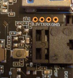
There is a reset button on the board, behind the SPDIF socket, though it cannot be triggered from the outside. There is a second set of serial pins, between the SD card slot and the USB 2.0 socket.
There is also a marking for an unpopulated cr1220/1225 battery holder for the RTC. Soldering the wires of a cr2032 case onto the square-ish pads works, the date/time survives a powerloss. Wire from top of battery goes to the pad nearest to the power barrel.
Adding a serial port (voids warranty)
Device disassembly
There is a small warranty sticker across one edge that needs to be cut to open the case.
Turn the device over, and slide a plastic tool around the edges of the bottom plate. This is just held in place with clips, there are NO screws hidden under the rubber feet. Lift the bottom place up. The PCB is held in place by three small Philips screws.
Locating the UART
The debug UART0 pins are located between the SPDIF and the USB3.0 socket, and are clearly labelled GND, RX, TX, 3.3V. Solder three wires there, and leave 3.3V unconnected. Connect to an adapter translating the 3.3V TTL logic level to something standard, so either USB or 12V RS232. The UART howto has more information.
Pictures
Take some pictures of your device, upload them, and add them here. DO NOT UPLOAD PICTURES WHICH YOU PLUCKED OFF THE INTERNET.
See also
Add some nice to have links here. This includes related devices, and external links.
Manufacturer images
Optional. Add non-sunxi images in this section.


