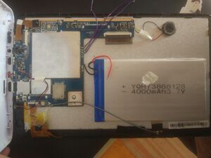
Vivax TPC-9150
| Vivax TPC-9150 | |
|---|---|
| Manufacturer | [1] |
| Dimensions | 238mm x 147mm x 9mm |
| Release Date | ? |
| Specifications | |
| SoC | A20 |
| DRAM | 1GiB DDR3 |
| NAND | 8GB |
| Power | USB 5V @ 1A, 4000mAh 3.7V Li-Ion battery |
| Features | |
| LCD | 1024x600 (9" 16:9) |
| Touchscreen | 5-finger capacitive (Focaltech FT5x06) |
| Video | HDMI (Type C - mini) |
| Audio | 3.5mm headphone plug, HDMI, internal mono speaker, internal microphone |
| Network | WiFi 802.11 b/g/n (Realtek RTL8723A) |
| Storage | µSD |
| USB | 1 USB2.0 OTG |
| Camera | 0.3MP (640x480) front, 2.0MP (1600x1200) rear |
| Other | Bluetooth (Realtek RTL8723AU) |
| Headers | UART |
Identification
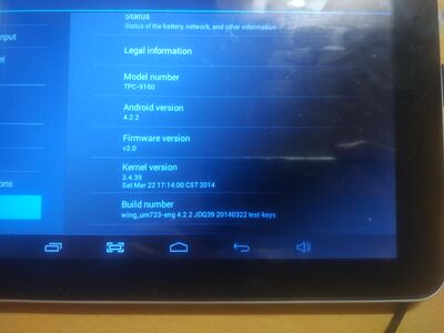
When booted into Android, open the "Settings" app and choose "About tablet". You will find the following information:
Model number: TPC-9150 Firmware version: v2.0 Kernel version: 3.4.39 Build number: wing_um723-eng 4.33 JDQ39 20140322 test-keys
Sunxi support
Legacy kernel support
Use the default sunxi kernel with the following FEX file
Mainline kernel support
Not yet merged.
Clone the Linux kernel from https://github.com/torvalds/linux
Apply the following patch (i.e. patch -p1 < file.patch)
After applying that run the following:
make ARCH=arm sunxi_defconfig
make ARCH=arm dtbs
Then afterwards use the desired sun7i-a20-tpc9150.dtb file with the latest mainline kernel.
Support status
Things that work:
- Accelerometer (hack required)
- Audio input (only via internal microphone)
- Audio output (only via headphone jack)
- SD card
- USB charging
- Battery indicator
- Battery charging
- Power management (via AXP209)
- Touchscreen and touchscreen wakeup
- Included LCD display
- Ability to control LCD brightness
- Wi-Fi
- Bluetooth
- UART
- HDMI
- HDMI audio
- Mali GPU (via lima driver)
- Power button
- USB slave (g_cdc and g_ether) work
- Suspend
- Charger hotplugging
Things that DO NOT work:
- The built-in speaker
- NAND (the driver lacks MLC support and thus fails to initialize the NAND chip, although it properly recognizes it)
- "ESC" key
- HDMI hotplugging (but firmware already probes manually)
- Both cameras
Things that are not tested (and probably don't work):
- USB OTG
Mainline U-Boot
Not yet merged.
Apply this patch with a freshly cloned U-Boot repository.
For building mainline U-Boot, use the Vivax_TPC9150 target.
UART, LCD, SD card work, nothing else does.
Manual build
Use the information in "Mainline kernel" and "Mainline U-Boot" along with the manual build howto, in order to build a functioning Linux system.
Tips, Tricks, Caveats
FEL mode
Following the FEL guide treat the "ESC" key as the FEL button.
Otherwise build an FEL SD card, using the same FEL guide and with a needle press the reset button, located on the back of the tablet.
Reset button
The reset button (on the back side of the device) reboots the device.
Internal µSD card
The device has an internal µSD card port that shows as mmcblk0. This port has boot priority over NAND.
Bad Wi-Fi range
The included Wi-Fi driver in most distros rtl8xxxu has really bad range on this device. It works, but Wi-Fi tends to cut off often.
In order to improve range use this driver instead: https://github.com/lwfinger/rtl8723au
Follow it's instructions, then blacklist the included rtl8xxxu driver.
Then to prevent the Wi-Fi connection from cutting off randomly, put the following into the /etc/modprobe.d/8723au.conf
options 8723au rtw_power_mgnt=0 rtw_enusbss=0 rtw_low_power=0 rtw_smart_ps=0
Suspend mode
The wake-up issue was fixed. However, the device can only be woken up by the touchscreen, as I was unable to find any interface from AXP209 to wake up the tablet.
How I fixed the issue: Anyway I've found this trick.
The original issue was that once the device was in suspend mode, the i2c2 bus would get stuck and the device will be unable to be controlled with. In order to fix this you'll need to add bias-pull-up; to your DTS like so:
&i2c2 {
	status = "okay";

	ft5x: touchscreen@38 {
		compatible = "edt,edt-ft5406";
		reg = <0x38>;
		interrupt-parent = <&pio>;
		interrupts = <7 21 IRQ_TYPE_EDGE_FALLING>; /* PH21 */

		touchscreen-size-x = <800>;
		touchscreen-size-y = <480>;

		wake-gpios = <&pio 1 13 GPIO_ACTIVE_HIGH>; /* PB13 */

		wakeup-source;
		bias-pull-up;
	};
};
Touchscreen does not work!!!! Help!
Please check that there aren't any udev rule files in /etc/udev/rules.d/ arbitrarily setting a libinput calibration matrix.
The accelerometer situation
For some reason the driver won't probe (or load) itself at boot, so you'll need to do it manually. This is a relatively simple process, just follow these steps:
- Make sure that the
stk8312module is available in your kernel - Manually probe it with:
modprobe stk8312 probe=1,0x3d - It should appear under
/sys/module/stk8312/drivers/i2c:stk8312/1-003d - To make changes persist across reboots, you'll need to create two files
- Create
/etc/modprobe.d/stk8312.confwith the contentoptions stk8312 probe=1,0x3d - Create
/etc/modules-load.d/stk8312.confwith the contentstk8312
- Create
- Reboot and see whether it worked, if it didn't then just run modprobe on each boot
The screen's a bit shifted, what's going on?
Basically there isn't a correct panel driver included into the current Linux source tree. Luckily, I have been successful in obtaining the correct LCD panel settings, but the problem is that I do not know the make or model of the LCD which would probably invalidate my kernel patch. Not only that, but manually patching this would require a kernel to be rebuild, which is too much effort in my opinion.
So the panel parameters that are available in the current patch are "good enough" in most use cases.
Adding a serial port (voids warranty)
Device disassembly
In order to open the device, there are two Phillips screws to remove from the side with the connectors. The pins from the white part are easy to pop but it is advised to use a a plastic tool, starting from opposite of the side with the connectors. The front panel is very fragile and pressuring the screen to pop open the pins can easily end up in breaking the touch screen panel.
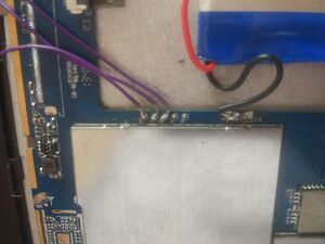
Locating the UART
The UART pads are located on the front side of the PCB. The UART pads are labeled and large enough so that soldering wires to those UART pins becomes easy.
