Sunchip SDK-758
| Sunchip SDK-758 | |
|---|---|
 | |
| Manufacturer | Sunchip |
| Dimensions | 101.6mm x 101.6mm x 23.6mm |
| Release Date | April 2014 |
| Website | Device Product Page |
| Specifications | |
| SoC | A20 @ 1Ghz |
| DRAM | 512MiB DDR3 @ 384MHz |
| NAND | 4 GB |
| Power | DC 5.6V @ 2A |
| Features | |
| Video | HDMI, Composite Video through 3.5mm jack |
| Audio | 3.5mm combined Composite AV plug, HDMI |
| Network | WiFi 802.11 b/g/n (Realtek RTL8188ETV), 10/100Mbps Ethernet (ICplus IP101GA) |
| Storage | µSD |
| USB | 1 USB2.0 Host, 1 USB2.0 OTG |
| Other | IRDA |
| Headers | UART |
This page needs to be properly filled according to the New Device Howto and the New Device Page guide.
Identification
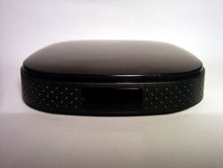
The case of this device has a very distinct and clean look. Other than that it reads the following printed information on the bottom:
[Android Logo]
ANDROID TELEVISION BOX
INPUT : 5V = 2A
[FCC] [CE] [Do not dispose]
MADE IN CHINA
On the bottom of the PCB it says: SDK-758-V1.0 2013-12-03
In android, under Settings->About Tablet, you will find:
- Model Number: CX_718
- Build Number: sugar_ref001-eng 4.2.2 JDQ39 20140507 test-keys
Sunxi support
Current status
Kernel and u-boot are currently WIP.
Images
HW-Pack
BSP
Manual build
- For building u-boot, use the "MANUFACTURER_DEVICE" target.
- The .fex file can be found in sunxi-boards as MANUFACTURER_DEVICE.fex
Everything else is the same as the manual build howto.
Mainline U-Boot
Mainline kernel
Tips, Tricks, Caveats
AV plug
The 3.5mm RCA AV jack has the following pinout:
Tip:    Composite
Ring 1: Audio Left
Ring 2: Audio Right
Base:   Ground
FEL mode
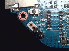
The "UBOOT" button triggers FEL mode. It is located between UART and the microSD slot. FEL mode is currently not too useful due to the lack of a standard OTG port, but perhaps a special USB Type-A (male-male) cable could work.
Adding a serial port (voids warranty)
Device disassembly
The top lid (shiny part) is held only by plastic notches. Insert your Plastic tool between top and bottom case vertically, and carefully work your way round.
Locating the UART
RX, TX and GND are clearly marked on the board right next to the microSD slot. Just solder on some wires according to our UART howto, or you can solder in some 2.54mm pitch connectors like in the picture.


