Olimex A13-OLinuXino
| Olimex A13-OLinuXino | |
|---|---|
 | |
| Manufacturer | Olimex |
| Dimensions | 120mm x 120mm x 20mm |
| Release Date | August 2012 |
| Website | Product Page |
| Specifications | |
| SoC | A13 @ 1Ghz |
| DRAM | 512MiB DDR3 @ 408MHz |
| NAND | 4GB (Optional) |
| Power | DC 6V-16V (1A @ 6V) |
| Features | |
| Video | VGA |
| Audio | 3.5mm headphone plug, 3.5mm microphone plug |
| Network | WiFi 802.11 b/g/n (Realtek RTL8188CTV - Optional) |
| Storage | µSD |
| USB | 3 USB2.0 Host (GL850G hub), 1 USB2.0 OTG |
| Other | RTC |
| Headers | UART, JTAG, Li-Po battery connector, LCD. UEXT, 2x GPIO expansions ports. |
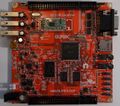
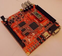
The A13-Olinuxino was the first Allwinner based development board made by Olimex. Like all Olimex hardware, it is fully Open Source Hardware.
Identification
It says "A13-OLinuXino" on the top. It just doesn't get easier than that!
Sunxi support
Current status
Supported.
Images
HW-Pack
BSP
Manual build
- For building u-boot, use the "A13-OLinuXino" target.
- The .fex file can be found in sunxi-boards as a13-olinuxino.fex
Everything else is the same as the manual build howto.
Mainline kernel
Use the sun5i-a13-olinuxino.dts device-tree file for the mainline kernel.
Tips, Tricks, Caveats
FEL mode
The Home button triggers FEL mode.
Power Supply Voltage
Warning, while you can boot this board at 5V it really is preferable to boot this board at 6V.
For instance, enabling the backlight on the 7" LCD module will immediately hardlock the board at 5V, while at 6V it is perfectly stable.
VGA
Even though the A13 does not provide DACs itself, the A13-Olinuxino has a VGA connector.
This is implemented through 3 separate DAC chips (NXP LVC244A) which are connected to the LCD0 lines. This in turn means that you cannot use an LCD and a VGA monitor at the same time, but this is ok as the A13 can only drive one display at a time anyway.
Due to the bandwidth limitations of the A13 SoC, the best resolution you can hope for is 800x600.
LCD modules
You can attach several Olimex LCD modules to the LCD connector (LCD_CON).
Expansion ports
Several expansion options are provided:
- A UEXT connector. This is meant for attaching Olimex UEXT modules.
- A 10 pin IO connector (GPIO-1).
- A 40 pin IO connector (GPIO-2).
Adding a serial port
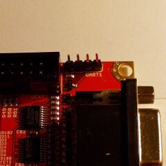
The earlier revisions of the A13-OLinuXino (Revisions A and B) had a separate UART1 connector which shared lines with the SD connector. You had to use the UART lines on the UEXT connector, to be able to use an SD card as well as serial.
From revision C onwards, there is the unpopulated UART0 connector, which shares those same lines with the SD Card lines. There is also a populated UART1 connector, which is standalone.
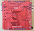
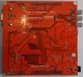
For a connector pin-out, the easiest way is to refer to the pin descriptions on the back of the board. Simply attach your leads according to our UART howto.
Pictures
Also known as
There are no rebadgers for this type of device.
See also
- Olimex A13-OLinuXino-Micro: a cut-down, cheaper version of this board.
- Other Olimex hardware
- User manual
- Olimex github repository with all CAD files and schematics.
