LicheePi Nano
| LicheePi Nano | |
|---|---|
 | |
| Manufacturer | Lichee-Pi |
| Dimensions | 25.4mm x 33.0mm |
| Release Date | 2018 |
| Website | [1] |
| Specifications | |
| SoC | F1C100s @ 408Mhz |
| DRAM | 32MiB DDR @ 24M~408MHz |
| Power | via GPIO pins or MicroUSB Jack |
| Features | |
| LCD | optional RGB LCD FPC |
| Touchscreen | optional |
| Audio | 2x speaker, 1x microphone via header pins |
| Network | WiFi 802.11 b/g/n (ESP8089) optional via µSD |
| Storage | µSD (not all models have slot), optional on-board 8MB, 16MB or 32MB SPI NOR Flash |
| USB | 1 USB2.0 OTG |
| Headers | SPI, I2C, UART |
This page needs to be properly filled according to the New Device Howto and the New Device Page guide.
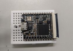
Tiny development board about the size of an SD card.
Identification
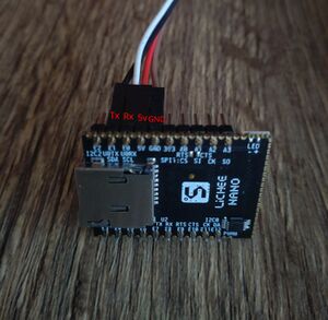
The PCB has the following silkscreened on it:
LiCHEE
NANO
Sunxi support
Images
Optional. Add MANUFACTURER DEVICE specific sunxi ROM images here. E.g. a livesuit image or some other linux image which uses linux-sunxi code. Do not put non-sunxi images here, they should live under See also. If no sunxi based images are available, this section can be removed.
Manual build
You can build things for yourself by following our Manual build howto and by choosing from the configurations available below.
Mainline U-Boot
Use the licheepi_nano_defconfig build target. Available since U-Boot v2022.04.
Mainline Linux Kernel
Use the suniv-f1c100s-licheepi-nano.dts device-tree tree binary.
Tips, Tricks, Caveats
Add MANUFACTURER DEVICE specific tips, tricks, Caveats and nice to have changes here.
FEL mode
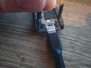
The FEL mode can be used over the on-board Micro-USB connector.
On models without on-board flash, just removing the SD Card triggers FEL mode.
On models with on-board SPI flash, according to the documentation you have the following options to enter FEL mode:
- "Short-circuit the 1 and 4 pins [those are VSS(GND) and CS] of the flash, power on again, release the short circuit after powering on"
- "Before booting to the kernel, press Enter to enter uboot and execute
sf probe 0;sf erase 0 0x100000;reset"
Both of these methods seem to be working, however keep in mind, that the latter erases the flash chip! This is only useful if you want to upload a new image anyway, otherwise use the first method!
Since one of the pins of the flash chip that need to be shorted to trigger FEL mode is GND, you can use any ground point and connect it to pin 4 of the flash chip. An easy way of doing this is to use the GND pin of the board, like depicted bellow.
After successfully triggering FEL mode, you should see the following USB device on your host:
Bus XXX Device XXX: ID 1f3a:efe8 Allwinner Technology sunxi SoC OTG connector in FEL/flashing mode
Device specific topic
If there are no further device specific topics to add, remove these sections.
Adding a serial port
The UART0 RX and TX pins are on PE0 and PE1, connected to the GPIO header pins, close to the microSD card slot. They are also marked as U0TX and U0RX. They carry the 3.3V level signal from the SoC, refer to the UART howto for more details.
Note: The board expose 2 UART interfaces by default (UART0 and UART2), you need UART0 for the boot console.
The stock software uses 115200 baud rate.
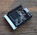
Pictures
Schematic
The schematic for the board can be found on the manufacturer's website: [2]
See also
Manufacturer images
Optional. Add non-sunxi images in this section.


