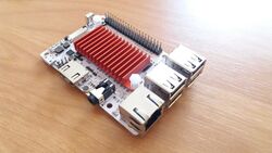
Libre Computer Board ALL-H3-CC
| Libre Computer Board ALL-H3-CC | |
|---|---|
 | |
| Manufacturer | Libre Computer Project |
| Dimensions | 83x55x18mm |
| Release Date | January 2018 |
| Website | ALL-H3-CC Product Page |
| Specifications | |
| SoC | H2+, H3, H5 @ 1.0GHz |
| DRAM | 512MiB, 1GiB, 2GiB DDR3 @ 1333MHz, h2+:H5TQ2G63GFR-RDC, h3/h5:H5TQ4G63CFR-RDC |
| Power | DC 5V @ 2A (µUSB) |
| Features | |
| Video | HDMI (Type A - full), CVBS |
| Audio | 3.5mm headphone plug, HDMI, SPDIF, I2S, internal microphone |
| Network | 10/100Mbps Ethernet |
| Storage | µSD, eMMC module port |
| USB | 3 USB2.0 Host, 1 USB2.0 OTG |
| Other | CIR |
| Headers | 3 pin UART, CSI, 40 pin GPIO |
The Libre Computer Board ALL-H3-CCs are H2+ / H3 / H5 powered development boards originally introduced via a Kickstarter campaign in 2017.
Points distinguishing this board from others:
- Raspberry Pi 3 compatible form factor
- eMMC 4.x module port (8/16/32/64/128GB)
- CE/FCC certification
- Big push-pin heatsink with thermal tape, covering SoC and ram
- Quality components, tier-1 ram chips
This board is produced in white colour and has 3 variants that only differ in SoC/ram used:
- ALL-H3-CC H2+ 512MB (Tritium IoT)
- ALL-H3-CC H3 1GB (Tritium 1GB)
- ALL-H3-CC H5 2GB (Tritium 2GB)
Otherwise dimensions, component and port locations are identical.
Identification
The PCB has the following silkscreened on it:
Libre Computer Board
ALL-H3-CC-V1.0-A
Sunxi support
Current status
The boards are supported by both mainline U-Boot and kernels.
Images
HW-Pack
BSP
Manual build
You can build things for yourself by following our Manual build howto and by choosing from the configurations available below.
U-Boot
Sunxi/Legacy U-Boot
Mainline U-Boot
Three build targets are provided, one for each board version:
- libretech_all_h3_cc_h2_plus_defconfig (H2+ board, since U-Boot v2018.07)
- libretech_all_h3_cc_h3_defconfig (H3 board, since U-Boot v2018.03)
- libretech_all_h3_cc_h5_defconfig (H5 board, since U-Boot v2018.07)
Linux Kernel
Sunxi/Legacy Kernel
Mainline kernel
Three device-tree binaries are provided, one for each board version:
- sun8i-h2-plus-libretech-all-h3-cc.dtb (H2+ board)
- sun8i-h3-libretech-all-h3-cc.dtb (H3 board)
- sun50i-h5-libretech-all-h3-cc.dtb (H5 board)
Expansion Port
Raspberry Pi model B+ compatible 40-pin, 0.1" connector with several low-speed interfaces.
| 2x20 Header | |||
|---|---|---|---|
| 1 | 3.3V | 2 | 5V |
| 3 | TWI0_SDA | 4 | 5V |
| 5 | TWI0_SCK | 6 | GND |
| 7 | CPUX-TDO/GPIO-1 | 8 | AP-UART1-TX |
| 9 | GND | 10 | AP-UART1-RX |
| 11 | CPUX-TCK/UART2-RX | 12 | BB-PCM-CLK |
| 13 | CPUX-TMS/UART2-TX | 14 | GND |
| 15 | CPUX-TDI/GPIO-2 | 16 | AP-UART1-CTS |
| 17 | 3.3V | 18 | AP-UART1-RTS/GPIO-3 |
| 19 | SPI0-MOSI | 20 | GND |
| 21 | SPI0-MISO | 22 | UART3-RX/SPI1-CLK/GPIO-4 |
| 23 | SPI0-CLK | 24 | SPI0-CS |
| 25 | GND | 26 | SPDIF/GPIO-5 |
| 27 | I2S0-SCLK/TWI1-SDA | 28 | I2S0-LRCK/TWI1-CLK |
| 29 | I2S0-SDO/GPIO-6 | 30 | GND |
| 31 | I2S0-SDI/GPIO-7 | 32 | UART3-TX/SPI1-CS0/GPIO-8 |
| 33 | PWM1 | 34 | GND |
| 35 | BB-PCM-SYNC | 36 | UART3-RTS/SPI1-MOSI/GPIO-9 |
| 37 | UART3-CTS/SPI1-MISO/GPIO-10 | 38 | BB-PCM-DIN |
| 39 | GND | 40 | BB-PCM-DOUT |
eMMC port
| 30-pin, 0.4mm connector (2x15) | |||
|---|---|---|---|
| 1 | VCC-NAND | 2 | NC |
| 3 | VCC-NAND | 4 | eMMC-CMD |
| 5 | VCC-NAND | 6 | GND |
| 7 | VCC-NAND | 8 | eMMC-D5 |
| 9 | VCC-NAND | 10 | eMMC-D4 |
| 11 | VCC-NAND | 12 | eMMC-D0 |
| 13 | NC | 14 | eMMC-D1 |
| 15 | NC | 16 | GND |
| 17 | NC | 18 | eMMC-D2 |
| 19 | NC | 20 | eMMC-D3 |
| 21 | NC | 22 | eMMC-D6 |
| 23 | NC | 24 | eMMC-D7 |
| 25 | GND | 26 | eMMC-RST |
| 27 | GND | 28 | GND |
| 29 | GND | 30 | eMMC-CLK |
Tips, Tricks, Caveats
Power
MicroUSB power is routed through 2A fuse (1F1). Connecting power through GPIO pins bypasses over voltage protection circuit. Each of USB-A jacks is routed through 500mA fuse (so you can not connect 1A HDD, also, you can not draw more than 500mA combined from the same dual-jack).
CPU power
H2+ and H3 boards supply single 1.2V to CPU using AXP8036 (1.1V on H5), which means maximum cpu freq is limited to 1008MHz.
USB-OTG
USB-OTG port is located in one of USB-A jacks. That's top left one on v1.0.
FEL mode
The U-BOOT button next the the µUSB connector triggers the FEL mode.
Buttons
- UBOOT (K1)
- Power (K2), PL2
LEDs
The board has three LEDs:
- Blue LED (Status), connected to the PA07 pin.
- Green LED (Power), connected to the PL10 pin.
- Red LED, connected to the VCC3V3-IR.
ESD & over-current protections
Based on the schematic Rev 1.0 (November 17, 2017) the board incorporates the following protections:
| Protections
x - no protection, ESD - Electrostatic Discharge, OC - Over-current |
Comments | |||
|---|---|---|---|---|
| 1 | USB micro (power) | ESD | OC (2A) | Input voltage limited to 5.6V, power supply bypass |
| 2 | Micro SD | x | x | |
| 3 | eMMC | x | x | |
| 4 | Camera | x | x | |
| 5 | Dual USB1 | ESD | OC (500mA) | Power supply bypass |
| 6 | Dual USB2 | ESD | OC (500mA) | Power supply bypass |
| 7 | HDMI | ESD | x | |
| 8 | Ethernet | ESD | N/A | Using TVS diodes connected deferentially, over-current protection is not applicable |
| 9 | GPIO | x | x | |
| 10 | Debug UART | ESD | ? | |
| 11 | Audio jack | ESD | N/A | Output current is internally limited by SoC |
Locating the UART
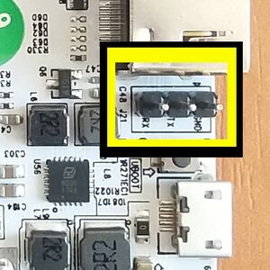
The UART pins are located between HDMI and power jack on the board. Marked on the PCB (simplified layout: ..board-edge..GND|TX|RX. Just attach some leads according to our UART Howto.


