LRADC
The Low Resolution Analogue Digital Converter (LRADC, also called KEYADC) is a simple ADC that is integrated in most Allwinner SoCs. With its 6-bit resolution and max 250 Hz sample rate it is limited to its intended use with a resistor network to connect several buttons to a single pin. The LRADC is connected to a single, non-multiplexed pin on the SoC.
The peripheral takes cares of the ADC conversion process, and provides interrupt functionality, to simplify driver design and efficiency for the input buttons use case.
Typical circuitry
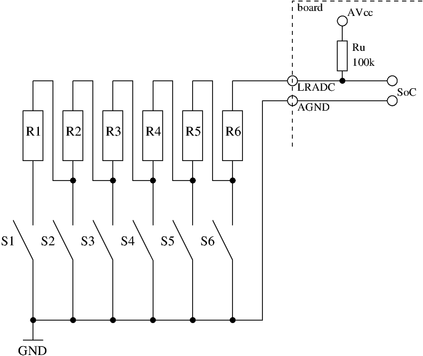
A typical circuit to connect buttons lets each switch connect a resistor to GND. As the different resistor values might be hard to come by, several smaller resistors values can be connected in series. Due to the mathematical properties of the voltage divider, the voltage difference gets smaller with each step, so bigger resistor values must be used for later buttons.
Typically the reference voltage is AVcc, which is 3.0V on most boards. The LRADC uses 3/4 (newer SoCs: 2.25V) or 2/3 (older SoCs: 2.0V) of that as its maximum voltage. Most boards contain a 100K pull-up resistor connected to AVcc, so the maximum resistor value against AGND should not exceed 300KOhm (or 200KOhm for older SoCs). The resolution is 35mV on a newer SoC, and 31mv on an older one.
To connect six buttons, you could use some circuit like this:
Due to the analogue nature of this circuit (inexact reference voltage, resistor tolerance, temperature effects, poor ADC conversion quality), the resistors should be chosen to give enough distance between the steps. The Linux driver will pick the button with the closest voltage, so the ADC readings should be at least 3 apart to give reliable results.
Useful resistor values for the above example could be 22KΩ for R1-R3, and 10KΩ for R4-R6. This will result in the following voltages and ADC values (on a "newer" SoC with 3.0V AVcc):
| Button | Rx value | accumulated R | voltage | ADC reading |
|---|---|---|---|---|
| S6 | 10K | 10K | 0.272V | 8 |
| S5 | 10K | 20K | 0.500V | 14 |
| S4 | 10K | 30K | 0.692V | 19 |
| S3 | 22K | 52K | 1.026V | 29 |
| S2 | 22K | 74K | 1.276V | 36 |
| S1 | 22K | 96K | 1.469V | 41 |
Devicetree example
Mainline Linux provides a driver (drivers/input/keyboard/sun4i-lradc-keys.c) for the LRADC device, which connects to the Linux input subsystem to offer key events on a /dev/input<x> device. Use CONFIG_KEYBOARD_SUN4I_LRADC if you use a custom kernel config. This is included in sunxi_defconfig (for ARM), but not selected for the arm64 defconfig.
Each button is described in its own child node within the LRADC devicetree node, naming a key value, a label and the voltage. A typical example looks like:
&lradc {
vref-supply = <®_avcc>;
wakeup-source;
status = "okay";
button-1 {
label = "Up";
linux,code = <KEY_VOLUMEUP>;
channel = <0>;
voltage = <272727>;
};
button-2 {
label = "Down";
linux,code = <KEY_VOLUMEDOWN>;
channel = <0>;
voltage = <500000>;
};
};
In this example the two buttons are connected with two 10KOhm resistors, given a 100K pull-up resistor and 3.0V AVcc this results in the above voltages.
If "reg_avcc" isn't already defined, a "regulator-fixed" node with 3.0V could be used. The key IDs for the linux,code property are defined in include/dt-bindings/input/linux-event-codes.h.
