Inet 86vs
| Inet 86vs | |
|---|---|
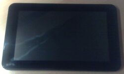 | |
| Manufacturer | iNet technology |
| Dimensions | 190 mm x 115mm x 9mm |
| Release Date | July 2013 |
| Website | 86VS Product Page |
| Specifications | |
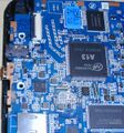
| SoC | A13 @ 1GHz |
| DRAM | 512MiB DDR3 @ 408MHz |
| NAND | 4GB |
| Power | 5V @ ?A, 2800mAh 3.7V Li-Ion battery |
| Features | |
| LCD | 800x480 (7" 16:9) |
| Touchscreen | 5-finger capacitive (Silead GSL1680) |
| Audio | 3.5mm headphone plug, internal speaker, internal microphone |
| Network | WiFi 802.11 b/g/n (Realtek RTL8188ETV) |
| Storage | µSD |
| USB | 1 USB2.0 OTG |
| Camera | 0.3MP (640x480) front |
| Other | Accelerometer (Manufacturer device FIXME), reset button |
| Headers | UART |
Identification
In android, under Settings->About Tablet, you will find:
- Model Number: MID705
- Build Number: A13_86VS_M758C1_1304117.20130629
Sunxi support
Current status
Supported.
WiFi reception is very poor probably due to bad antenna.
Tested:
- boot from SD card - mmc0
- PMU
- original nand flash content access
- LCD
- USB OTG (ethernet gadget)
- USB HOST (wifi)
- tablet keys
Don't work:
- touchscreen
- networking
Untested (should work):
- mali
- cedar
Detected by kernel but needs testing:
- rtc
- USB WiFi
- audio
Unknown:
- accelerometer
- camera
Images
HW-Pack
BSP
Manual build
- For building u-boot, use the INet_86VS target.
- The .fex file can be found in sunxi-boards as inet_86.fex
Everything else is the same as the manual build howto.
Tips, Tricks, Caveats
FEL mode
The VOL+ button triggers FEL mode.
Alternatively, there is a pad labeled u-boot near the wifi. Connecting this to ground also triggers FEL mode. Pads for a UBOOT button are also available on the board.
Adding a serial port (voids warranty)
Some pads are available on the board, but they are multiplexed with the SD card. So use a MicroSD Breakout board. The ones from Sparkfun or DX should work with the cover on, but you have to remove the back cover to attach the cubietech one.
Device disassembly
Be careful to first remove the SD Card.
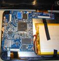
The tablet has screws next to the connectors. The board is on the display part and the bottom cover is removed. Remove the screws and pry the bottom cover open with your plastic tool.
Make sure the USB port is inserted into the cover first when reassembling.
Locating the UART
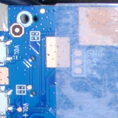
UART is marked on the bottom of the PCB (between the PCB and display) and on the top under the tape holding ctp connector. Both connect to the SD slot so you can as well use a SD breakout board. The FEX file does not enable UART.
UART1 pins are used for CSI and connected to a 24pin 0.5mm pitch FFC connector which is used for camera. Probing with a multimeter confirms that the console pins seem to be connected somewhere around the middle of the connector. The pitch is the same as IDE ZIF connector but IDE is 40pin.
It is possible to use a generic ffc and an IDE ZIF to 3.5" adaptor to connect to the pins routed to CSI. I can confirm using the u-boot gpio command that the pins actually connect to the ide connector when the cable is inserted properly but I cannot get the console working. Unfortunately the 24pin cable gets loose easily in 40pin connector.
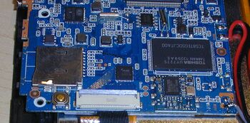
Pictures
Also known as
Rev1.0 was marketed as
Rev2.0 (documented) was sold as:
