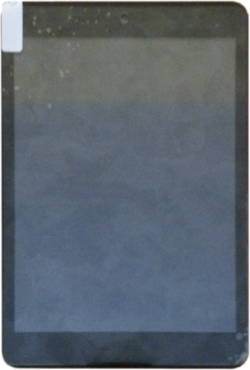
ICOU Fatty I
| ICOU Fatty I | |
|---|---|
 | |
| Manufacturer | ICOO |
| Dimensions | 135mm x 200mm x 7mm |
| Release Date | July 2013 |
| Website | Device Product Page |
| Specifications | |
| SoC | A20 @ 1Ghz |
| DRAM | 1GiB DDR3 @ 384MHz |
| NAND | 8GiB |
| Power | DC 5V @ 2A, 3500mAh 3.7V Li-Ion battery |
| Features | |
| LCD | 768x1024 (7.85" 3:4) |
| Touchscreen | 5-Finger Capacitive (Ilitek aimvF) |
| Video | HDMI (Type C - mini) |
| Audio | 3.5mm headphone plug, HDMI, internal stereo speakers, internal microphone |
| Network | WiFi 802.11 b/g/n (Realtek RTL8188ETV) |
| Storage | µSD |
| USB | 1 USB2.0 OTG |
| Camera | 0.3MP (640x480) front, 2.0MP (1600x1200) rear |
| Other | Accelerometer (Freescale MMA7660) |
| Headers | UART |
Identification
The PCB has the following silkscreened on it:
2013-04-10
TOPWISE-013
S785F-MAINBOARD-V2.0.0
In Android, under Settings->About Tablet, you will find:
- Model Number: Fatty1
- Build Number: 20130601-S785
Sunxi support
Current status
There is neither mainline U-Boot nor mainstream kernel support at this point.
The legacy U-Boot properly supports the device.
Some features are missing on Linux (sunxi-3.4 branch):
- USB OTG doesn't work on the external connector (common to all sun7i devices) and it doesn't seem to work in either host or device mode
- LCD does not work (it uses MIPI), but backlight works
- Wi-Fi doesn't work (interface is never ready)
- HDMI doesn't work (segfault)
Manual build
- For building u-boot, use the "ICOU_Fatty_I" target.
- The .fex file can be found in sunxi-boards as icou_fatty_i.fex
Everything else is the same as the manual build howto.
Tips, Tricks, Caveats
FEL mode
The VOL- button triggers FEL mode. This is the third button from the top on the right edge of the device.
Adding a serial port (voids warranty)
Device disassembly
Opening the device is really straightforward. There are two Phillips screws to remove on top of the device and once these are out, the back aluminium case can easily be removed using a plastic tool to pop a few pins.
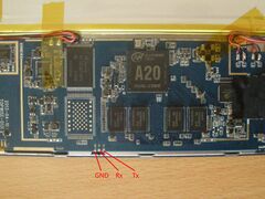
Locating the UART
The UART pads are clearly labeled on the PCB: GND, Rx, Tx. These pads are located on the edge of the board, left and below the RAM chips. All you have to do is solder on some wires according to our UART howto.


