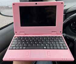
Honlin HL-1013-A133P
| Honlin HL-1013-A133P | |
|---|---|
 | |
| Manufacturer | Manufacturer |
| Dimensions | widthmm x breadthmm x heightmm |
| Release Date | Month year |
| Website | Device Product Page |
| Specifications | |
| SoC | A133 @ XGhz |
| DRAM | 2GiB LPDDR3 @ xxxMHz |
| eMMC | 32GiB |
| Power | DC 5V @ 2A, 3600mAh 3.7V Li-Ion battery |
| Features | |
| LCD | 1024x600 (6.98" ~16:9) |
| Audio | 3.5mm headphone+mic plug, internal stereo speakers, internal microphone |
| Network | WiFi 802.11 b/g/n (Xradio Tech XR829) |
| Storage | SD (full size) |
| USB | 2x USB2.0 Host, 1x USB2.0 OTG |
| Camera | ??.?MP (????x????) front |
This page needs to be properly filled according to the New Device Howto and the New Device Page guide.
Identification
There aren't any obvious manufacturer or branding markings on the case.
On Amazon US, it is listed as:
Goldengulf
GG-789-A133
The PCB has the following silkscreened on it:
Efercro
NA70_MB_V1.3
In android, under Settings->About Tablet, you will find:
- Model Number: HL_1013_A133P
- Build Number: HL_1013_A133P_US_20230725
Sunxi support
Current status
Not supported yet.
Manual build
You can build things for yourself by following our Manual build howto and by choosing from the configurations available below.
U-Boot
Use the MANUFACTURER_DEVICE build target.
Linux Kernel
Use the FAMILY-CHIP-DEVICE.dtb device-tree binary.
Tips, Tricks, Caveats
The OTG port is accessible via the USB-C power input port at the rear of the device. It can be used for ADB access from another system.
FEL mode
There is a tiny button underneath the keyboard, accessible via a cutout on the right side, near the USB-A ports.
Running "adb reboot efex" from a host connected to the OTG port also works when the device is booted into the stock Android OS.
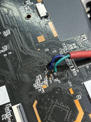
Adding a serial port (voids warranty)
This section explains how to attach a serial port to the device. Make sure it refers to our UART howto. For a development board, you can just mention how to find the header with the pins and include a picture, and you can remove the warranty voiding warning.
Device disassembly
- Remove the LCD assembly. There are screws underneath the 4 rubber pads in the corners. Use a plastic tool to disengage the clips holding the two halves of the LCD assembly together. There are 3 clips each on the left, right, and bottom edges, and 4 clips on the top edge.
- Remove the keyboard. There are 4 latches near the "ESC", "F4/F5", "F9/F10", and "Delete" keys.
- Remove the screws on the bottom of the device. There is one clip by the touchpad on the front edge.
Locating the UART
There are pads on the PCB with "RX", "TX", and "GND" silkscreen labels nearby. UART is active, solder wires to the pads. The UART howto will be useful.
Pictures
Pictures of the outside will be added at a future date. In the meanwhile, some can be found on Amazon's product page (see below).


