FriendlyARM NanoPi NEO2
| FriendlyARM NanoPi NEO2 | |
|---|---|
 | |
| Manufacturer | FriendlyARM |
| Dimensions | 40mm x 40mm |
| Release Date | Apr 2017 |
| Website | NanoPi NEO2 |
| Specifications | |
| SoC | H5 @ 816 Mhz |
| DRAM | 512MiB DDR3 |
| Power | DC 5V @ 2A via microUSB or pin headers |
| Features | |
| Audio | microphone, stereo line-out, I²S and S/PDIF on pin headers |
| Network | 10/100/1000Mbps Ethernet (Realtek RTL8211E) |
| Storage | µSD |
| USB | 1 USB2.0 Type A, 2 USB2.0 pin header, OTG µUSB |
| Headers | UART, SPI, I²C, 2x USB2.0 Host, analog audio, microphone |
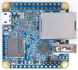
NanoPi NEO 2 is a H5 based small form-factor development boards produced by FriendlyARM. It has the same form factor than the previous NanoPi NEO, but with H5 instead of the H3 SoC. The NEO comes with integrated 1000 Mbps Ethernet, 1 x USB A 2.0, and a micro-SD card slot. A lot of functionality is provided via the unpopulated headers on both boards.
Identification
Sunxi support
Current status
The H5 SoC support has matured since its introduction in kernel 4.12. Most of the board functionality for boards such as FriendlyARM NanoPi NEO2, including 3D graphics, hardware accelerated video and crypto, and DVFS are available with current mainline kernels. Only a very few minor features are still being worked on. For a more comprehensive list of supported features, see the status matrix for mainline kernels.
See the Manual build section for more details.
BSP
FriendlyELEC started in March to switch from Allwinner BSP to an own mainline kernel fork currently remaining at 4.11.2 where DT files can be found. Same with mainline u-boot. Important: They're not following upstream conventions and eg. DRAM configuration in u-boot is done entirely different. That means community members relying blindly on FriendlyELEC gihub repos are prone to submit wrong stuff upstream!
Manual build
You can build things for yourself by following our Manual build howto and by choosing from the configurations available below.
U-Boot
Mainline U-Boot
Use the nanopi_neo2_defconfig (supported since v2017.07) build target.
Linux Kernel
Sunxi/Legacy Kernel
Mainline kernel
The H5 SoC has support in the mainline kernels.
The development process, links to patches and links to kernel fork repositories are listed on the Linux mainlining effort page. Patches can also be found from the arm-linux mailing list.
Repositories with H5 patches:
- Ondřej Jirman's branch for H5 based orange Pi (kernel 4.19) (work-in-progress DVFS)
- Thermal regulation (if CPU heats above certain temperature, it will try to cool itself down by reducing CPU frequency)
- HDMI audio support (from Jernej Skrabec)
- Configure on-board micro-switches to perform system power off function
- Wireguard (https://www.wireguard.com/)
Use the sun50i-h5-nanopi-neo2.dtb device-tree binary.
Expansion Port
Tips, Tricks, Caveats
FEL mode
There is no FEL button on this board. Booting without an SD card automagically enters FEL mode.
./sunxi-fel version
AWUSBFEX soc=00001718(H5) 00000001 ver=0001 44 08 scratchpad=00017e00 00000000 00000000
LEDs
Two leds: a blue connected to PA10 labeled 'status' and a green one connected to PL10 labeled 'pwr'.
Voltage regulators
FriendlyELEC implemented no CPU voltage regulation on this board so H5 is fed all the time with 1.1V only which limits maximum clockspeed to 816 MHz based on DVFS table provided by Allwinner BSP.
DRAM
NanoPi NEO is available with 512 MiB but only in single bank configuration.
USB
The one USB host port exposed as type A receptacle is usb3. Both usb1 and usb2 are available via solder holes. USB OTG available through Micro USB.
Analog Audio
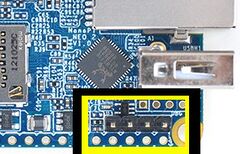
On NanoPi NEO 2 analog audio out and mic in is available on 5 pin header next to USB receptacle. Please check FriendlyELEC wiki or schematic for details.
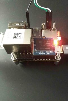
Adding a serial port
Locating the UART
Four-pin UART0 header is placed next to analog audio pin header. Pinout: GND, 5V, TX, RX. Pin 1 (GND) is the one furthest from the board edge. Logic voltage is 3.3V. For more instructions refer to our UART Howto.
Pictures
NanoPi NEO 2
Variants
NanoPi NEO Core2
In the NEO Core2 variant, the ethernet and USB A connectors are replaced with unpopulated headers (similar to NanoPi NEO Core). The variant also comes with onboard eMMC (4GB/8GB/16GB/32GB).
NanoPi NEO2 Black
In the NEO2 Black variant an eMMC socket is provided. The pins for UART0 have to be soldered in by the user.
See also
Manufacturer images
See the manufacturer's device pages above since links change from time to time.


