FriendlyARM NanoPi M1
| FriendlyARM NanoPi M1 | |
|---|---|
 | |
| Manufacturer | FriendlyARM |
| Dimensions | 64mm x 56mm |
| Release Date | March 2016 |
| Website | NanoPi M1 Product Page |
| Specifications | |
| SoC | H3 @ 1.2Ghz |
| DRAM | 512MiB (K4B2G1646D-BCK0) or 1GiB (K4B4G1646D-BCK0) DDR3 |
| Power | DC 5V @ 2A via microUSB or pin headers |
| Features | |
| Audio | microphone, stereo line-out, I²S and S/PDIF on pin headers |
| Network | 10/100Mbps Ethernet (H3 built-in PHY) |
| Storage | µSD |
| USB | 3 USB2.0 Host, 1 USB2.0 OTG |
| Headers | UART, SPI, I²C, 2x USB2.0 Host, analog audio, microphone |
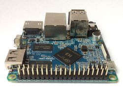
NanoPi M1 is H3 based development board produced by FriendlyARM. Feature-wise it is very similar to Orange Pi PC.
Identification
Almost square board, blue soldermask, ⌀3mm mounting holes in the corners. 3 x USB type-A, Ethernet jack (with integrated magnetics) and four-pin header for UART/power near one of the edges. Sticker indicating amount of RAM is placed on the lower PCB side.
On the top side of the board, next to H3 SoC, the following is silkscreened:
FRIENDLYARM
NanoPi-M1
(on LinkSprite's OEM variant 'pcDuino4 nano' can be read instead)
Sunxi support
Current status
The H3 SoC support has matured since its introduction in kernel 4.2. Most of the board functionality for boards such as NanoPi M1 are available with current mainline kernels. Some features (hw accelerated crypto, hw spinlocks, and thermal) are still being worked on. For a more comprehensive list of supported features, see the status matrix for mainline kernels. In addition, legacy 3.4 kernels are available in various work-in-progress git branches.
See the Manual build section for more details.
NanoPi M1 shares nearly all hardware details with Orange Pi PC (same number of USB ports) and Orange Pi One (same voltage regulator). Besides the differences regarding camera connector and pins available on the GPIO header pretty similar to Orange Pi PC. Detailed device information can be found on FriendlyArm wiki.
Images
FriendlyARM's and 3rd partie's OS images can be found here. Armbian images with more recent u-boot and kernel versions can be found here.
BSP
FriendlyARM provides a BSP based on a newer Allwinner 3.4.39 variant on Github.
Manual build
You can build things for yourself by following our Manual build howto and by choosing from the configurations available below.
U-Boot
Mainline U-Boot
Use the nanopi_m1_defconfig build target (supported since v2017.07) build target. The U-Boot repository and toolchain is described in the Mainline U-Boot howto.
The H3 boards can boot from SD cards, eMMC, NAND or SPI NOR flash (if available), and via FEL using the OTG USB port. In U-Boot, loading the kernel is also supported from USB or ethernet (netboot). HDMI support in U-Boot is still WIP.
Linux Kernel
Sunxi/Legacy Kernel
The 3.4 kernel from the official Allwinner's git repository does not support H3 yet. But it is possible to use one of the kernel forks, based on the lichee H3 SDK tarball:
- Siarhei Siamashka's branch '20151207-embedded-lima-memtester-h3'
- Yann Dirson's fork added a few more fixes and adopted most of
- Boris Lovosevic' great initial work on Allwinner's H3 kernel
Configure this kernel using sun8i_h3_defconfig, the rest is explained in the kernel compilation guide.
Use the .fex file for generating script.bin. The .fex file is available from xunlong_orange_pi_pc.fex.
When booting the legacy 3.4 kernel with the mainline U-Boot, add the following line to boot.cmd:
  setenv machid 1029
  setenv bootm_boot_mode sec
Some other legacy kernel repositories:
- 3.4-lichee-based kernel, based on work by ssvb and loboris
- Yocto support here glues together all the required parts to get this kernel to work with mainline u-boot, as well as accelerated X11/GLES support
- A newer H3 BSP variant appeared with tons of fixes which has been made available by FriendlyARM.
- A cleaned up fork has been adopted by Armbian project. On top of that Armbian maintains a bunch of 3.4.x patches for H3 devices.
Mainline kernel
The mainline kernel has good support for the H3 SoC. Please refer to the status matrix for a more detailed list of the development process, links to patches and links to kernel fork repositories. Minor drivers that are currently work-in-progress may require a) third party patches (see also arm-linux mailing list) or b) a pre-patched distro (e.g. Armbian).
Repositories with H3 patches:
- Ondřej Jirman's branch for H3 based orange Pi (kernel 4.19) (work-in-progress DVFS)
- Thermal regulation (if CPU heats above certain temperature, it will try to cool itself down by reducing CPU frequency)
- HDMI audio support (from Jernej Skrabec)
- Configure on-board micro-switches to perform system power off function
- Wireguard (https://www.wireguard.com/)
- Philipp Rossak's THS patches (in the sunxi-ths- branches)
- Corentin Labbe's HW Crypto and spinlock patches (in respective branches)
Use the sun8i-h3-nanopi-m1.dtb device-tree binary.
Tips, Tricks, Caveats
FEL mode
No FEL button. The device falls into FEL mode when no SD card is inserted.
LEDs
The board has two LEDs, mounted on the top side next to the audio jack:
- A red LED, labelled "PWR", connected to the PL10 pin and to 3.3V via weak pull-up, thus being able to represent three states:
- full brightness when GPIO is set to output high
- reduced brightness when GPIO is set to high impedance state
- turned off when GPIO is set to output low.
- A blue LED, labelled "STAT", connected to the PA10 pin.
JTAG
Connect gnd and target voltage to any of the gnd and vcc3v3-ext pins on the 2x20 expansion connector. Pin 22 (uart2_rx) is TCK, pin 11 (uart2_tx) is TMS, pin 15 (uart2_cts) is TDI and pin 13 (uart2_rts) is TDO.
The JTAG sel pins that seem to be used to enable JTAG at chip power on aren't broken out but you can enable JTAG on the expansion connector once uboot has started with this command (add it to boot script and compile boot.scr again to make it permanent):
mw.l 0x01c20800 0x77223333 1
OpenOCD configuration should look something like this (based on the config from this page in Japanese):
source [find interface/ftdi/dp_busblaster_kt-link.cfg]
adapter_khz 300
transport select jtag
reset_config none
gdb_breakpoint_override hard

if { [info exists CHIPNAME] } {
   set  _CHIPNAME $CHIPNAME
} else {
   set  _CHIPNAME sun8iw7
}

if { [info exists DAP_TAPID] } {
    set _DAP_TAPID $DAP_TAPID
} else {
    set _DAP_TAPID 0x5ba00477
}

jtag newtap $_CHIPNAME dap -expected-id $_DAP_TAPID -irlen 4 -ircapture 0x01 -irmask 0x0f

set _TARGETNAME0 $_CHIPNAME.cpu0
set _TARGETNAME1 $_CHIPNAME.cpu1
set _TARGETNAME2 $_CHIPNAME.cpu2
set _TARGETNAME3 $_CHIPNAME.cpu3

target create $_TARGETNAME0 cortex_a -chain-position $_CHIPNAME.dap -coreid 0
target create $_TARGETNAME1 cortex_a -chain-position $_CHIPNAME.dap -coreid 1
target create $_TARGETNAME2 cortex_a -chain-position $_CHIPNAME.dap -coreid 2
target create $_TARGETNAME3 cortex_a -chain-position $_CHIPNAME.dap -coreid 3
target smp $_TARGETNAME0 $_TARGETNAME1 $_TARGETNAME2 $_TARGETNAME3

$_TARGETNAME0 configure -event gdb-attach {
    cortex_a dbginit
}
$_TARGETNAME1 configure -event gdb-attach {
    cortex_a dbginit
}
$_TARGETNAME2 configure -event gdb-attach {
    cortex_a dbginit
}
$_TARGETNAME3 configure -event gdb-attach {
    cortex_a dbginit
}
This is a little bit fragile but it works well enough to set breakpoints in the kernel with GDB so should be useful when debugging drivers etc.
Voltage regulators / heat
NanoPi M1 uses the same voltage regulator as Orange Pi One/Lite switching between 1.1V and 1.3V (SY8113B datasheet). Unlike the Xunlong boards which contain a thick copper layer inside the PCB to spread heat away from the SoC FriendlyARM chose a different design. This and maybe the smaller PCB size lead to higher temperatures compared to Orange Pis and in case you want to operate the M1 under constant high load think about adding a heatsink
Adding a serial port
Locating the UART
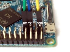
Four-pin UART0 header is placed next to 40 pin GPIO header. Pinout: GND, 5V, TX, RX. Pin 1 (GND) is the one next to Micro USB connector. Logic voltage is 3.3V. For more instructions refer to our UART Howto.
Pictures
Variants
- FriendlyARM did the pcDuino4 nano as OEM for Linksprite which will be sold starting in September 2016. According to cnxsoft both models are compatible.
NanoPi M1+
FriendlyARM introduced an improved version, the NanoPi M1+ in March 2017. This variant adds with 802.11n WiFi, Bluetooth, and integrated eMMC. All the connectors except for the micro USB OTG and camera ports are also on one side for easier access. The third USB port is provided via additional header pins. The positions of the HDMI and Ethernet ports have also been switched.
ESD & over-current protections
Based on the schematic Rev 1702 (May 18, 2017) the board incorporates the following protections:
| Protections
x - no protection, ESD - Electrostatic Discharge, OC - Over-current |
Comments | |||
|---|---|---|---|---|
| 1 | USB micro (power) | ESD | x | Uses a combination of ideal diode and TVS |
| 2 | Micro SD | ESD | x | |
| 5 | Dual USB | ESD | x | Power supply bypass |
| 7 | HDMI | ESD | x | |
| 8 | Ethernet | x | N/A | Over-current protection is not applicable |
| 9 | GPIO | x | x | |
| 10 | Debug UART | x | OC | Uses resistors to limit the current |
| 11 | Audio jack | ESD | N/A | Output current is internally limited by SoC |
See also
Manufacturer images
- Linux and Android images: https://www.mediafire.com/folder/3q2911p1qp33p/NanoPi-M1Board


