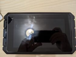
Creality Sonic Pad
| Creality Sonic Pad | |
|---|---|
 | |
| Manufacturer | Shenzhen Creality 3D Technology Co., Ltd |
| Dimensions | 222mm x 40mm x 128mm |
| Release Date | September 2022 |
| Website | [1] |
| Specifications | |
| SoC | R818 @ 1.5Ghz |
| DRAM | 2GiB DDR4 |
| NAND | none |
| Power | DC 5V @ 3A, 3700mAh 3.7V Li-Ion battery |
| Features | |
| LCD | 1024x600 (7" 16:9) |
| Touchscreen | X-finger capacitive/resistive (Goodix GT9xx) |
| Video | lcd |
| Audio | internal speaker |
| Network | WiFi 802.11 b/g/n (XR819), 10/100/1000Mbps Ethernet (RTL8211F) |
| Storage | 8GiB SanDisk eMMC |
| USB | 4 USB2.0 Host |
| Camera | none |
| Other | External SPI for included ADXL345 G-Sensor |
| Headers | none |
This page needs to be properly filled according to the New Device Howto and the New Device Page guide.
The Creality Sonic Pad is a 3D printing tablet, running a modified version of Klipper.
Identification
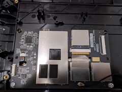
On the top side of the device, a sticker states the model as "S-Pad 01". The mainboard has "SONIC-L_MBOARD V1004" silkscreened onto it. The SoC, PMU, and one other chip are rebadged as Creality parts.
Sunxi support
Current status
No support yet.
Manual build
You can build things for yourself by following our Manual build howto and by choosing from the configurations available below.
U-Boot
Mainline U-Boot
There is no support for mainline U-Boot on this device yet.
Linux Kernel
Mainline kernel
No device tree compatible with the mainline kernel exists for this device yet. However, patches are in the process of being upstreamed for the A100.
Tips, Tricks, Caveats
- In the Tina Linux
vqmmc-supplyis set as DCDCE, when in fact it is controlled by ALDO1. Modifying this allows the eMMC to run at 1.8V, allowing to run the eMMC at HS200 speeds. Other side effects have yet to be determined.
FEL mode
There are two buttons hidden inside holes on the back of the device. While the device is off, use a paperclip to push in the one closest to the side, and power on the device.
To communicate with the device, you will need a USB-A to USB-A cable. Attach one end to the USB port labelled "CAM" on the back of the device, and plug the other end into your computer.
Adding a serial port (voids warranty)
There is no UART connector on this device, but there are through-holes you can solder to. Please ensure you've read and understood the risks and consequences of making this modification before continuing.
Device disassembly
Unscrew the 4 Mx? screws on the back of the pad. Carefully remove the back of the shell; there is a wire connecting the internal speaker to one of the daughterboards. Unscrew the 4 Philips screws on the heatsink, and gently remove it to avoid damaging the thermal pads.
Locating the UART
UART is located on at the top of the board Jx?. The order is as follows, from left to right: 1. RX 2. TX 3. GND
You will need to solder jumper wires and then reassemble your device. Figure out how you want to route them, then use one of the many programs available to talk to the device; ensure your baud rate is set to 115200.


