LeMaker Banana Pro
| LeMaker Banana Pro | |
|---|---|
 | |
| Manufacturer | LeMaker |
| Dimensions | 92mm x 60mm |
| Release Date | October 2014 |
| Website | Banana Pro Product Page |
| Specifications | |
| SoC | A20 @ 1GHz |
| DRAM | 1GiB DDR3 @ 432MHz |
| NAND | no onboard NAND |
| Power | DC 5V @ 2A (via micro usb) |
| Features | |
| Video | HDMI (Type A - full), CVBS |
| Audio | 3.5mm TRRS plug (combined A/V out), HDMI, internal microphone |
| Network | WiFi 802.11 b/g/n (Ampak AP6181 ,first test batch with RTL8189ES instead), 10/100/1000Mbps Ethernet (Realtek RTL8211E) |
| Storage | µSD, SATA (with power connector) |
| USB | 2 USB2.0 Host, 1 µUSB2.0 OTG |
| Other | IrDA |
| Headers | 3 pin UART, LCD/ LVDS, CSI, 40 pin GPIO, WiFi external antenna connector (Hirose U.FL) |
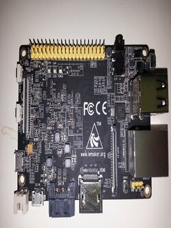
The Banana Pro is essentially an updated version of the Banana Pi. Unlike its predecessor, this device features a microSD ("TF") slot, onboard WLAN and a 40 pin GPIO header (that mimics the Raspberry Pi A+/B+ models). To make room for the additional GPIO pins, the analog A/V output is combined into a single TRRS type 3.5mm connector.
Identification
At least 3 different PCB revisions exist. The first pre-production version featured a RTL8189ES Wi-Fi chip instead of the AP6181 used for the production versions. The letters "BANANA PRO" were printed on the bottom side of the PCB. The second batch with AP6181 had also "BANANA PRO" on the bottom between DRAM and HDMI connector. Later batches came without this lettering.
All Banana Pro PCBs are black with yellow expansion headers, and the LeMaker Logo is printed on the upper side of the PCB. The Banana Pro can be differentiated from the other SBCs LeMaker tries to sell starting from June 20th 2015 by looking at the A20 SoC.
Sunxi support
Current status
Supported.
Images
HW-Pack
BSP
Manual build
- The "legacy" community u-boot-sunxi does not support the Banana Pro. Use mainline U-Boot instead (see below), or try the version from LeMaker's repository.
- The .fex file can be found in sunxi-boards as lemaker_banana_pro.fex
Everything else is the same as the manual build howto.
Mainline U-Boot
Use the Bananapro_defconfig build target. The U-Boot repository and toolchain is described in the Mainline U-Boot howto.
Mainline kernel
Use the sun7i-a20-bananapro.dtb device-tree file for the mainline kernel. Note this patch if you get wifi "brcmf_attach: dongle is not responding" errors with 4.17 to 5.x kernels.
Expansion Port
The Banana Pro has a 40-pin, 0.1" connector with several low-speed interfaces.
| 2x20 Header | |||
|---|---|---|---|
| 1 | 3.3V | 2 | 5V |
| 3 | TWI2-SDA | 4 | 5V |
| 5 | TWI0-SCK | 6 | GND |
| 7 | IO-1 | 8 | UART4-TX |
| 9 | GND | 10 | UART4-RX |
| 11 | UART2-RX | 12 | PWM1 |
| 13 | UART2-TX | 14 | GND |
| 15 | UART2_CTS | 16 | IO-4(CAN-TX) |
| 17 | 3.3V | 18 | IO-5(CAN-RX) |
| 19 | SPI0_MOSI | 20 | GND |
| 21 | SPI0_MISO | 22 | IO-6(UART2_RTS) |
| 23 | SPI0_CLK | 24 | SPI0_CS0 |
| 25 | GND | 26 | SPI0_CS1 |
| 27 | TWI3-SDA | 28 | TWI3-SCK |
| 29 | IO-7(IR0_TX/SPDIF_MCLK) | 30 | GND |
| 31 | UART7_RX | 32 | UART7_TX |
| 33 | IO-8(SPDIF_DO) | 34 | GND |
| 35 | I2S0_LRCK | 36 | I2S0_BCLK |
| 37 | I2S0_MCLK | 38 | I2S0_DI |
| 39 | GND | 40 | I2S0_DO0 |
Tips, Tricks, Caveats
FEL mode
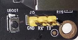
The UBOOT button, located next to the three UART pins (J15), triggers FEL mode.
Combined Audio+Video
According to "answer" in http://www.lemaker.org/thread-12417-1-1.html, the pinout of the TRRS connector is (from tip to sleeve) "Left, Right, Video, Ground". This is unconfirmed but would mean it's not the same as on the new Raspberry PIs, and instead would be similar to some MP3players (according to http://www.raspberrypi-spy.co.uk/2014/07/raspberry-pi-model-b-3-5mm-audiovideo-jack/).
Adding a serial port
Locating the UART
The UART pins are located in the lower right corner of the board (connector J15) - they are marked as GND, RX and TX on the PCB. Just attach some leads according to our UART Howto.
Powering the board
When no 2.5" SATA disk is used the board can also be powered more reliable through the SATA-power-connector since this connector and the normal power-in Micro USB connector located between SATA and SATA-pwr are connected directly.
Pictures
Also known as
Variants
- SinoVoip produced a different version of called "M1Plus" (BPi-M1+) as a Banana Pro rip-off sharing exactly the same hardware specs and almost the same position of onboard connectors. Main difference: SoC, DRAM and PMU are on the upper side of the PCB whereas on the lower on Banana Pro. Featurewise both boards are nearly identical and fex/dts files can be interchanged directly, with one small exception: according to LeMaker's and Sinovoip's fex files, [audio_pa_ctrl] differs: PH26 on M1+ and PH15 on Banana Pro. It turned also out that the blue led is red and connected to PH25 instead of PG02.
| deviating Pins of 2x20 Header | |||
|---|---|---|---|
| 29 | PB5(I2S_MCLK) | 30 | GND |
| 31 | PB6(I2S_BCLK) | 32 | PB12(I2S_DI) |
| 33 | PB7(I2S_LRCK) | 34 | GND |
| 35 | PB8(I2S_DO0) | 36 | PI21(UART7_RX) |
| 37 | PB3(IR0_TX) | 38 | PI20(UART7_TX) |
| 39 | GND | 40 | PB13(SPDIF_DO) |
as of linux 4.17-5.3.1 you might need to modify dts to make wifi working: https://patchwork.kernel.org/patch/10621433/
See also
- LeMaker Banana Pi (→ Banana Pi variants)
- LeMaker's Github Repository
- hardware-libre.fr article that has a good overview of this device, including detailed pictures.
- File:Banana Pro Schematic.pdf
Manufacturer images
- Various prebuilt images are provided via LeMaker's Website, adapted to work with the Banana Pro.


