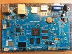
Merrii Hummingbird A31
| Merrii Hummingbird A31 | |
|---|---|
 | |
| Manufacturer | Merrii |
| Dimensions | 160 mm x 100 mm |
| Release Date | June 2014 |
| Website | Device Product Page |
| Specifications | |
| SoC | A31 @ 1Ghz |
| DRAM | 1GiB/2GiB DDR3 @ 312MHz |
| NAND | 8/16GB |
| Power | DC 12V @ 3A |
| Features | |
| Video | HDMI (Type A - full), VGA, TV IN |
| Audio | 3.5mm headphone plug, 3.5mm line-in plug, HDMI, on-board microphone |
| Network | WiFi 802.11 b/g/n + BT (AP6210), 10/100/1000Mbps Ethernet (Realtek RTL8211(E?)) |
| Storage | µSD |
| USB | 2 USB2.0 Host, 1 USB2.0 OTG |
| Headers | UART, JTAG, LCD, SPI, TWI, RTP, CSI, MIPI CSI, MIPI DSI, Speakers (amplified) |
Identification
The board reads "Quad-Core HummingBird Kit"
The board comes with Android 4.2.2 (3.3.0 kernel) preloaded in the NAND.
- Model Number: Softwinner
- Build Number: fiber_3g-eng 4.2.2 JDQ39 20140521 test-keys
Sunxi support
Current status
The Hummingbird A31 is only partially supported.
Images
HW-Pack
BSP
Manual build
No support in the community maintained sunxi-3.4 kernel is planned. Please skip to the next Mainline U-Boot/Mainline kernel sections.
Mainline U-Boot
Supported in the mainline u-boot git 'master' branch and scheduled for the v2015.04 release.
For building mainline u-boot, use the Hummingbird_A31 target.
Mainline kernel
Mainline kernel support is included in 3.17. Currently only UARTs, USB, I2C, and GMAC are supported. HDMI/VGA display is support with the latest mainline u-boot using simplefb.
Use the sun6i-a31-hummingbird.dtb device-tree file for the mainline kernel.
Tips, Tricks, Caveats
FEL mode
The UBOOT button triggers FEL mode. See BROM for more information on the boot sequence.
VGA out
The Hummingbird A31 uses an external DAC (GM7123), numbered U6 on the board, to convert output from LCD0 (TCON0) to RGB.
No configuration is required, other than enabling power to the chip, using GPIO PH25.
Note: DDC is not supported.
TV In
The Hummingbird A31 uses a low power TV decoder chip for TV in. The chip's output is connected to CSI on the PE pin group. It is controlled via I2C on TWI0. Power is controlled with GPIO PH26.
Datasheet
GM7150 datasheet (CN) (pdf, 38 pages)
Expansion Ports
The Hummingbird A31 exposes 2 2.54 mm pitch connectors with lots of expansion possibilities.
| J4 "TO LCD Board" (Near mini PCIe slot) | |||
|---|---|---|---|
| 2x60 Header | |||
| 1 | VCC-5V | 2 | VCC-5V |
| 3 | VCC-5V | 4 | GND |
| 5 | GND | 6 | GND |
| 7 | GPIO-PD1-LCD-D1-LVDS0-VN0 | 8 | GPIO-PD0-LCD-D0-LVDS0-VP0 |
| 9 | GPIO-PD3-LCD-D3-LVDS0-VN1 | 10 | GPIO-PD2-LCD-D2-LVDS0-VP1 |
| 11 | GPIO-PD5-LCD-D5-LVDS0-VN2 | 12 | GPIO-PD4-LCD-D4-LVDS0-VP2 |
| 13 | GND | 14 | GND |
| 15 | GPIO-PD7-LCD-D7-LVDS0-CLKN | 16 | GPIO-PD6-LCD-D6-LVDS0-CLKP |
| 17 | GPIO-PD9-LCD-D9-LVDS0-VN3 | 18 | GPIO-PD8-LCD-D8-LVDS0-VP3 |
| 19 | GPIO-PD11-LCD-D11-LVDS1-VN0 | 20 | GPIO-PD10-LCD-D10-LVDS1-VP0 |
| 21 | GPIO-PD13-LCD-D13-LVDS1-VN1 | 22 | GPIO-PD12-LCD-D12-LVDS1-VP1 |
| 23 | GPIO-PD15-LCD-D15-LVDS1-VN2 | 24 | GPIO-PD14-LCD-D14-LVDS1-VP2 |
| 25 | GND | 26 | GND |
| 27 | GPIO-PD17-LCD-D17-LVDS1-CLKN | 28 | GPIO-PD16-LCD-D16-LVDS1-CLKP |
| 29 | GPIO-PD19-LCD-D19-LVDS1-VN3 | 30 | GPIO-PD18-LCD-D18-LVDS1-VN3 |
| 31 | GPIO-PD21-LCD-D21 | 32 | GPIO-PD20-LCD-D20 |
| 33 | GPIO-PD23-LCD-D23 | 34 | GPIO-PD22-LCD-D22 |
| 35 | GPIO-PD24-LCD-CLK | 36 | GPIO-PD25-LCD-DE |
| 37 | GPIO-PD27-LCD-VSYNC | 38 | GPIO-PD26-LCD-HSYNC |
| 39 | GPIO-PH27-LCD-BL-EN | 40 | GPIO-PH13-PWM0 |
| 41 | GPIO-PC27-LCD-PWR-EN | 42 | GPIO-PA24-TP-WAKEUP |
| 43 | TP-X1 | 44 | GPIO-PA23-TP-INT |
| 45 | TP-X2 | 46 | GPIO-PH16-TWI1-SCK |
| 47 | TP-Y1 | 48 | GPIO-PH17-TWI1-SDA |
| 49 | TP-Y2 | 50 | VCC-3V |
| 51 | DSI-D0P (MIPI) | 52 | DSI-D0N (MIPI) |
| 53 | DSI-D1P (MIPI) | 54 | DSI-D1N (MIPI) |
| 55 | DSI-D2P (MIPI) | 56 | DSI-D2N (MIPI) |
| 57 | DSI-D3P (MIPI) | 58 | DSI-D3N (MIPI) |
| 59 | DSI-CKP (MIPI) | 60 | DSI-CKN (MIPI) |
| J11 (Near USB Ports) | |||
|---|---|---|---|
| 2x60 Header | |||
| 1 | VCC-5V | 2 | VCC-5V |
| 3 | VCC-3V | 4 | VCC-3V |
| 5 | GPIO-PE0-CSI-PCLK | 6 | GPIO-PH14-CSI-SCK (TWI0) |
| 7 | GPIO-PH15-CSI-SDA (TWI0) | 8 | GPIO-PE3-CSI-VSYNC |
| 9 | GPIO-PE2-CSI-HSYNC | 10 | GPIO-PE1-CSI-MCLK |
| 11 | GPIO-PE8-CSI-D4 | 12 | GPIO-PE9-CSI-D5 |
| 13 | GPIO-PE10-CSI-D6 | 14 | GPIO-PE11-CSI-D7 |
| 15 | GPIO-PE12-CSI-D8 | 16 | GPIO-PE13-CSI-D9 |
| 17 | GPIO-PE14-CSI-D10 | 18 | GPIO-PE15-CSI-D11 |
| 19 | GND | 20 | GND |
| 21 | CAM-RESET# | 22 | GPIO-PH28-CAM-STBY-EN |
| 23 | CSI-1V5 | 24 | CSI-1V8 |
| 25 | GPIO-PE7-CSI-PWREN | 26 | AFVCC-2V8 |
| 27 | GPIO-PE6-CSI-AF-IO | 28 | CSI-2V8 |
| 29 | GND | 30 | GND |
| 31 | CSI2-D0N (MIPI) | 32 | CSI2-D0P (MIPI) |
| 33 | CSI2-D1N (MIPI) | 34 | CSI2-D1P (MIPI) |
| 35 | CSI2-D2N (MIPI) | 36 | CSI2-D2P (MIPI) |
| 37 | CSI2-D3N (MIPI) | 38 | CSI2-D3P (MIPI) |
| 39 | CSI2-CKN (MIPI) | 40 | CSI2-CKP (MIPI) |
| 41 | MIPI-CSI-MCLK | 42 | GND |
| 43 | GND | 44 | GPIO-PH18-TWI2-SCK |
| 45 | GPIO-PE6-UART5-RX | 46 | GPIO-PH19-TWI2-SDA |
| 47 | GPIO-PE5-UART5-TX | 48 | GPIO-PH9-SPI2-CS0 |
| 49 | GPIO-PA6-UART1-RTS | 50 | GPIO-PH10-SPI2-CLK |
| 51 | GPIO-PA7-UART1-CTS | 52 | GPIO-PH11-SPI2-MOSI |
| 53 | GND | 54 | GPIO-PH12-SPI2-MISO |
| 55 | GPIO-PA5-UART1-RX | 56 | GPIO-PM4 |
| 57 | GPIO-PA4-UART1-TX | 58 | GPIO-PM5 |
| 59 | VCC-3V | 60 | GPIO-PM6 |
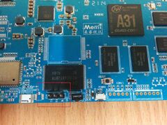
Adding a serial port
The UART header is right next to the NAND chip and IR receiver. Just attach some leads according to our UART howto.


