MSI Primo73
| MSI Primo73 | |
|---|---|
 | |
| Manufacturer | MSI |
| Dimensions | 196mm x 121mm x 9.5mm |
| Release Date | November 2013 |
| Website | Device Product Page |
| Specifications | |
| SoC | A20 @ 1Ghz |
| DRAM | 1GiB DDR3 @ 384MHz (Nanya NT5CB256M16BP-DI) |
| NAND | 16GB |
| Power | USB, 3000mAh 3.7V Li-Ion battery |
| Features | |
| LCD | 1024x600 (7" 16:9) |
| Touchscreen | 5-finger capacitive (Goodix GT911) |
| Video | HDMI (Type C - mini) |
| Audio | 3.5mm headphone plug, HDMI, internal speaker, internal microphone |
| Network | WiFi 802.11 b/g/n (Realtek RTL8188ETV - 0bda:0179) |
| Storage | µSD |
| USB | 1 USB2.0 OTG |
| Camera | 0.3MP (640x480) front, 2.0MP (1600x1200) rear |
| Other | Accelerometer (Freescale MMA8452) |
| Headers | Internal UART, JTAG; unidentified test points |
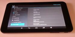
This is a brand name tablet from a reputable hardware vendor, so no problems with identification are expected. The tablet has a sturdy metal back cover and the overall build quality is good. However the TN display has relatively poor contrast and viewing angles (at least when compared with IPS displays), the wireless antenna is poorly connected (center and shield are sometimes shorted!), and the battery is hard-soldered to the mainboard.
Identification
There is a clearly visible MSI PRIMO 73-031PL label on the back of the tablet. It simply can't be mistaken with anything else.
Information about the Android firmware: http://www.androiddevice.info/submission/18728/show
Sunxi support
Current status
Supported by the legacy u-boot-sunxi and sunxi-3.4 kernel. LCD display works. WLAN, touchscreen and accelerometer are untested yet.
The mainline kernel support is seriously hindered by the missing USB OTG driver. But WLAN can be used to connect with the outside world and at least do something semi-useful with the device. HDMI works. The LCD display is supported by recent patches, but they have not landed to the mainline releases yet.
Images
HW-Pack
BSP
Manual build
- For building u-boot, use the "MSI_Primo73" target.
- The .fex file can be found in sunxi-boards as msi_primo73.fex
Everything else is the same as the manual build howto.
Mainline U-Boot
Supported in the mainline u-boot git 'master' branch and scheduled for the v2015.04 release.
For building mainline u-boot, use the MSI_Primo73 board name.
Mainline kernel
A patch has been sent to the mailing list and if it gets accepted, then it will be possible to use sun7i-a20-primo73.dtb.
For now, you can download the patch and apply it manually:
If you used git to download your kernel, you can apply the patch using the following line-- which should be executed from the directory where you've cloned the kernel:
wget http://linux-sunxi.org/images/a/a4/Primo73_mainline.patch -O- | git apply
If you downloaded the kernel source without git (e.g. by downloading a tarball), you can apply the patch as easily:
wget http://linux-sunxi.org/images/a/a4/Primo73_mainline.patch -O- | patch -p1
You can then build the kernel via the instructions in the Mainline_Kernel_Howto.
Tips, Tricks, Caveats
FEL mode
The VOL+ button triggers FEL mode. Actually both of the volume control buttons are directly connected to the UBOOT_SEL pin and drive it low when pressed, as can be easily verified by reading the BOOT_SEL_PAD_STA bits from SRAM_VER_REG. This is nice, but does not add any extra unbrickability value, because the SD card has the highest boot priority on any A10/A13/A20 device and already can be used for recovery.
Use as a GNU/Linux desktop machine
A MiniHDMI cable can be used to connect a big desktop monitor. Something like a USB OTG Charging Hub accessory may allow using USB peripherals (keyboard, mouse, ethernet adapter, etc.) and supplying power to the tablet at the same time. This setup works fine with the legacy sunxi-3.4 kernel.
Note that the USB OTG support is still not ready in the mainline kernel at the moment.
Adding a serial port
A serial port is a near-essential tool when developing for the Primo 73, as the tablet only has limited support for external keyboards and mice via USB OTG. It may be possible to get by without one-- but for any serious development, you should strongly consider adding a UART ("serial port") and saving yourself the trouble.
Fortunately, there are two methods for adding a UART to the Primo 73:
- You can use the SD card port as a simple serial port. This typically requires use of a MicroSD Breakout Board, an inexpensive PCB which can be used in place of a normal SD card. This method requires no disassembly, but the SD card adapter uses the same data lines as "normal" communication with the SD card; so you can't use a SD card while using this method. You can still boot linux over USB via FEL. This method should not void your warranty.
- You can open your tablet, and manually solder wires to its internal UART port. This method will void your warranty, and requires some skill with a soldering iron. If you don't know what you're doing-- or if you don't have the proper equipment-- you can easily damage your device! This method has the advantage of leaving the SD card port free for use by the tablet.
Both methods require use of a 3.3.V LVTTL serial to USB cable (or a 3.3V to RS-232 level changer, if your computer has a serial port).
UART via MicroSD breakout
It is possible to temporarily abandon the SD card slot and instead gain UART serial console by using a MicroSD Breakout accessory. This is useful for low level u-boot/kernel debugging without any need to dismantle the device. Even without the SD card, the system (u-boot + kernel + initramfs) still can be booted over a MicroUSB cable by using the FEL/USBBoot mode provided by BROM.
To get this working, you'll need a MicroSD Breakout, and the patience to make several minor changes to the u-boot and kernel configurations. You can find instructions and more information about the process on the MicroSD Breakout page.
Device disassembly
If you've decided to add a hard-wired serial port, you'll need to disassemble your tablet. It is assumed that the reader has some experience with disassembling electronic devices--- and is aware of the fact that disassembly will likely void their device's warranty. A careless disassembly may also damage your tablet, so be careful!
To open the tablet, you'll need the following tools:
- A small phillip's head screwdriver, for removing the mainboard; and
- A plastic non-mar disassembly tool; sometimes called a "spludger". You can open these devices without a non-mar tool-- but as the name implies, using other tools will aesthetically damage your device. A non-mar tool is recommended.
To open the device, place your plastic tool between back and front housing pieces and push them apart. It's suggested that you start near the connectors at the top of the device-- near the front cameras-- and gradually work your way to the bottom. Be careful not to slide your plastic tool in too far-- you don't want to press against the LCD screen or battery.
Once the back cover has been removed, the device has been laid bare! You'll likely want to remove the various insulating and heat-sink stickers; but be careful to note their positions-- you'll want to replace them before reassembling your device.
Locating the UART
Unfortunately, the UART headers (and all of the other test points) are located on the back of the mainboard-- so you'll need to remove the mainboard in order to access them. This is made more difficult by the wireless antenna and battery, which have been soldered directly to the mainboard rather than using a more robust connector. Note that, due to the battery, parts of your device will remain on as you work-- so you'll need to be careful not to short anything out!
Next, remove the mainboard from the chassis:
- Detach each of the flat-flex "ribbon" cables from the board. There are two types of flat-flex cable connectors: some of them have securing tabs that "flip up" (including the camera and touchscreen connectors), while others have tabs that "slide out" (including the main LCD panel).
- Remove the two cameras, which share a single ribbon cable, from the main-board by sliding their detatched ribbon cable forward-- towards the edge of the PCB. Place them aside.
- Optional: If you'd like, you can desolder the battery to make the board easier to work with. Carefully de-solder the two battery wires. As you desolder them, be careful to avoid shorting the positive and negative terminals together! Shorting out a lithium-polymer battery can be quite dangerous-- it's recommended that you cover one or both of the battery leads with insulating ("electrical") tape to avoid a nasty short.
- Detach the wireless antenna. There are two ways to accomplish this: you can detach the antenna from the chassis, or desolder the coaxial antenna cable from the PCB. Either should work-- if you opt to desolder the antenna, be careful to keep the center conductor and shield of the antenna separate.
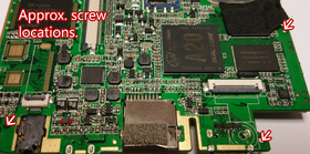
- Remove each of the three Philip's head screwdrivers that secure the mainboard to the chassis. They may be hard to find, and at least one of them may be partially obscured by a sticker. To aide you, each of the screws has been identified in the picture to the right.
- If you opted not to desolder the battery, carefully detach it from the chassis.
- Lift the speaker off of the LCD. The speaker is attached both with a magnet and some weak adhesive, a gentle pull should be enough to liberate it.
- Lift the mainboard up and out of the device. If you have any peripherals still soldered to the mainboard (i.e. the speaker, battery and antenna wire), carefully lift them out with the mainboard.
Next, flip the board over, and carefully remove any of the insulating tape pressed against the bottom of the board. Be careful to note its location-- as you'll need to put it (or something equally flat and nonconductive) over the exposed pads during reassembly. You should now see a multitude of test points exposed!
Soldering the UART
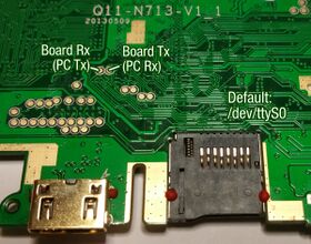
Using the diagram to the right, identify the receive (Rx) and transmit (Tx) test pads: you'll likely want to solder thin wires to these pads, so you can use them for development. Wire-wrapping wire tends to work particularly well for this kind of prototyping; they can easily be routed out of the device.
Solder wires to each of the following locations:
- Receive (Rx), the small pad shown in the picture the right;
- Transmit (Tx), also shown in the picture to the right; and
- Ground (GND), which is not shown. The rectangular pad directly underneath the PCB's ID number ("Q11-N713-V1_1") is an easy-to-access ground point.
If you opted not to disconnect the battery, be careful not to short anything! Your soldering iron, wires, and solder should only ever touch one contact a at a time! Be sure you have all cables disconnected, so your board isn't grounded: most soldering irons have grounded tips.
Bringing out the UART
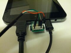
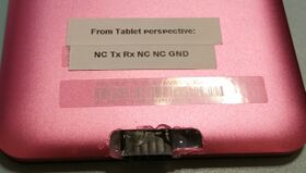
Once you've soldered in your UART, you're ready to bring the signals out to a place where you can get to them! Fortunately, the Primo 73 seems to have an unpopulated cutout in the bottom of its case-- perhaps intended for a dock connector-- which comes filled with a plastic placeholder. The placeholder is simply taped in, and can easily be pushed out-- leaving a nice location for a debug header! If you have a female socket that will fit in that slot, you can make a debug header which keeps the device relatively portable (for Linux development on the go, of course!).
Once you have your UART brought out, you'll likely want to connect to your PC and try things out! More information is available on the UART page.
Pictures
Pictures of the MSI Primo 73, in and out:
Display quality comparison with MSI Primo81:
See also
Manufacturer images
The manufacturer provides a PhoenixSuit recovery image at http://www.msi.com/product/tablet/support/Primo_73.html#down-firmware
