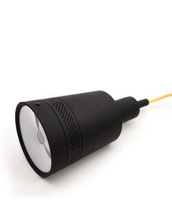
KOHOTECH KP100 MB V3.0
| KOHOTECH KP100 MB V3.0 | |
|---|---|
 | |
| Manufacturer | KOHO |
| Dimensions | 150mm x 110mm |
| Release Date | 02 2015 |
| Website | Device Product Page |
| Specifications | |
| SoC | A20 @ 1Ghz |
| DRAM | 1GiB DDR3 @ 384MHz |
| NAND | 4GB |
| Power | AC 230V @ 0.5A |
| Features | |
| LCD | 854 x 480 |
| Touchscreen | no |
| Video | LCD |
| Audio | PAM8403 audio amplifier |
| Network | WiFi 802.11 b/g/n (Ampak AP6210) |
| Storage | NAND, µSD (assembly variant) |
| USB | 1 USB2.0 Host (assembly variant), 1 USB2.0 OTG (assembly variant) |
| Camera | N/A |
| Other | N/A |
| Headers | N/A |
This page needs to be properly filled according to the New Device Howto and the New Device Page guide.
If a device is special, then feel free to provide a terse description of what makes this device so special. But terse, no novels, no marketing blurb.
Identification
On the back of the device, the following is printed:
Beam
v1.01
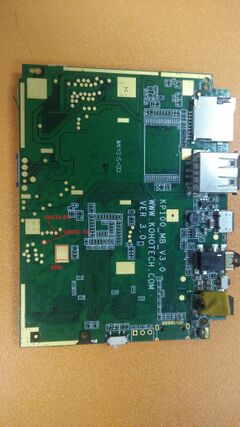
The PCB has the following silkscreened on it:
KP100_MB_V3.0
In android, under Settings->About Tablet, you will find:
- Model Number: Template:Beam
- Build Number: Template:KRT16S
Sunxi support
Current status
Fex file added to sunxi-boards Give a brief overview of the current status of support under sunxi here.
Manual build
You can build things for yourself by following our Manual build howto and by choosing from the configurations available below.
U-Boot
Sunxi/Legacy U-Boot
Use the MANUFACTURER_DEVICE build target.
Mainline U-Boot
Use the MANUFACTURER_DEVICE build target.
Linux Kernel
Sunxi/Legacy Kernel
Use the MANUFACTURER_DEVICE.fex file.
Mainline kernel
Use the FAMILY-CHIP-DEVICE.dtb device-tree binary.
Tips, Tricks, Caveats
Add MANUFACTURER DEVICE specific tips, tricks, Caveats and nice to have changes here.
FEL mode
The something button triggers FEL mode.
Device specific topic
If there are no further device specific topics to add, remove these sections.
...
Adding a serial port (voids warranty)
This section explains how to attach a serial port to the device. Make sure it refers to our UART howto. For a development board, you can just mention how to find the header with the pins and include a picture, and you can remove the warranty voiding warning.
Device disassembly
If necessary, provide a short description of how to open the device. Perhaps explain how the pins can be most easily popped. If pins do need to be popped, mention the Plastic tool howto.
Locating the UART
The UART pins are jus tsome testpads hidden on the bottom side of the PCB. It requires opening up the device to get to them!
Also known as
List rebadged devices here.
See also
Add some nice to have links here. This includes related devices, and external links.

