LeMaker Banana Pi
| LeMaker Banana Pi | |
|---|---|
 | |
| Manufacturer | LeMaker |
| Dimensions | 92 mm x 60 mm |
| Release Date | April 2014 |
| Website | Banana Pi Product Page |
| Specifications | |
| SoC | A20 @ 1 GHz |
| DRAM | 1 GiB DDR3 @ 432 MHz |
| NAND | no (onboard) NAND available |
| Power | DC 5 V @ 2 A (micro USB) |
| Features | |
| Video | HDMI (Type A - full), CVBS, LVDS |
| Audio | 3.5 mm headphone plug, HDMI, internal microphone |
| Network | 10/100/1000 Mbps Ethernet (Realtek RTL8211E) |
| Storage | SD, SATA (with power connector: JST XH 2.5mm header, providing +5V) |
| USB | 2 x USB 2.0 Host, 1 x USB 2.0 OTG |
| Other | IR receiver |
| Headers | 2 pin UART, 8 pin UART (including power source), LCD/ LVDS, CSI, 26 pin GPIO |
The Banana Pi (also known as Banana Pi M1) is trying very hard to mimic the formfactor of the Raspberry Pi and to cash in on its popularity, but it fails to match both the exterior dimensions, the exact connector placing and the software support.
Despite manufacturer claims of being open source, this is not open source hardware. If you are thinking of getting this device, you should also try looking into the hardware from our Community instead. There is also little actual support to be had from LeMaker (and even less from SinoVoip), mostly they are just rehashing things from the linux sunxi community.
The Banana Pi has clearly suffered from having different manufacturers/distributors each favor their competing model variants and create their own (sub)"communities". On top of that there were clashes and legal disputes over trademarks and domain ownership. Quite often it would be unclear who's officially responsible for a particular device, and what degree of support the vendor provided. This has created confusion among users, and contradicted the collaborative approach that could be expected from the "open (source)" marketing label they unanimously used.
A 2015-05-23 statement describes the current state of things, and gives some historical background information[1]. It remains to be seen whether the situation will improve in the future. (This 2015-08 follow up seems to indicate the contrary.)
In 2015-11 the person behind Xunlong (Orange Pi) claimed he was paid to do the ODM work for Banana Pi in the beginning.
The Lemaker domain lapsed between September and November of 2021, the status of the company is currently unclear.
Identification
The current PCB revision 1.4 has the following silkscreened on it (usually hidden below a barcode label):
BP-A20
(PCB revisions 1.01[2] and 1.3[3] were labeled with exact version number, and 1.4 was also produced in a green PCB version)
Sunxi support
Current status
Supported.
Current mainline U-Boot (v2015.04) and mainline kernel (3.19.2+) work well on the Banana Pi. Kernel 4.0+ is recommended, as it adds cpufreq support for A20 SoCs (allowing lower power consumption and reduced temperatures).
Manual build
- The .fex file can be found in sunxi-boards as lemaker_banana_pi.fex
- For building U-Boot, use the Bananapi target (
make Bananapi_defconfig).
Everything else is the same as the manual build howto.
 Note: Banana Pi's GMAC is not supported in the community ("sunxi-3.4") kernel. If you want proper gigabit networking support, you'll either have to use one of the later kernels diverged from the 3.4.x line (e.g. the ones from LeMaker, Igor Pečovnik or Daniel Andersen), or a 4.1+ mainline kernel - in combination with a suitable U-Boot version (v2015.04 and up).
- The key point is that the GMAC driver needs to be specifically instructed to set the GMAC_TX_DELAY parameter to 3. This adjusts the relative timing of the clock and data signals to the PHY, in order to compensate for differing trace lengths on the PCB. Without this modification, the Ethernet port will work at 100 Mbit, but not (or not reliably) at 1000 Mbit. Upstream U-Boot now sets this parameter itself, so the kernel patch isn't needed any more. For details, see also: Ethernet#GMAC
Mainline U-Boot
If booting your 3.4.x kernel fails with "Error: unrecognized/unsupported machine ID", you need to adjust your U-Boot config or patch the kernel - see troubleshooting. In case it completely refuses to boot / gets stuck right after "booting the kernel", make sure that bootm_boot_mode=sec is set.
Mainline kernel
Use the sun7i-a20-bananapi.dtb device-tree file, and follow the Mainline Kernel Howto.
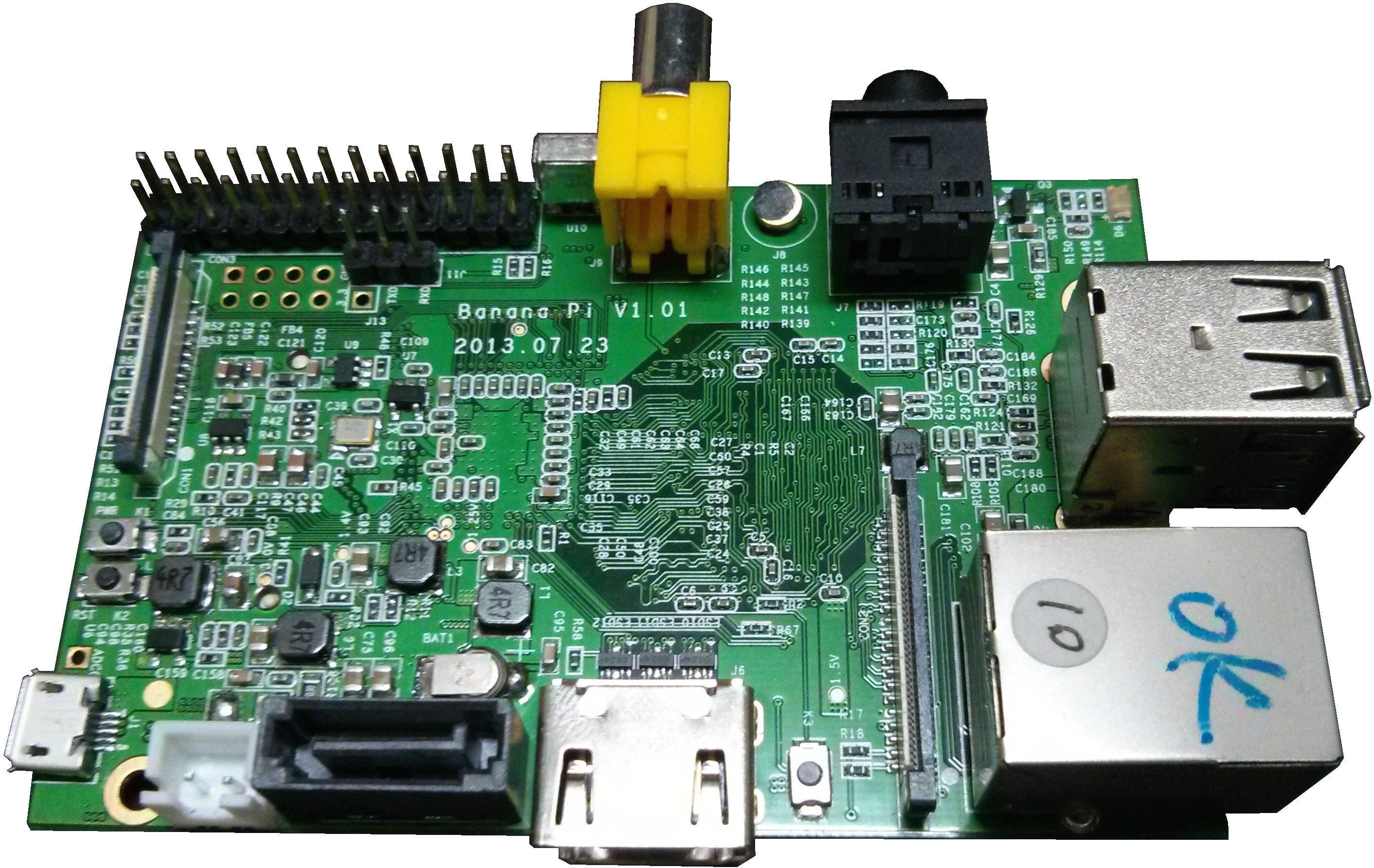
Expansion Port

The Banana Pi has a 26-pin, 0.1" connector with several low-speed interfaces.
| 2x13 Header | ||||||||
|---|---|---|---|---|---|---|---|---|
| 3.3V | 1 | 2 | 5V | |||||
| PB21 | I2C2_SDA | 3 | 4 | 5V | ||||
| PB20 | I2C2_SCK | 5 | 6 | GND | ||||
| I2C4_SDA / PWM1 | PI3 | GPCLK | 7 | 8 | UART3-TX | PH0 | LCD1_D0 / EINT0 / CSI1_D0 | |
| GND | 9 | 10 | UART3-RX | PH1 | LCD1_D1 / EINT1 / CSI1_D1 | |||
| SPI1_MISO / UART2_RX / EINT31 | PI19 | IO-0 | 11 | 12 | IO-1 | PH2 | LCD1_D2 / UART3_RTS / EINT2 / CSI1_D2 | |
| SPI1_MOSI / UART2_TX / EINT30 | PI18 | IO-2 | 13 | 14 | GND | |||
| SPI1_CLK / UART2_CTS / EINT29 | PI17 | IO-3 | 15 | 16 | IO-4 | PH20 | LCD1_D20 / CAN_TX / EINT20 / CSI1_D20 | |
| 3.3V | 17 | 18 | IO-5 | PH21 | LCD1_D21 / CAN_RX / EINT21 / CSI1_D21 | |||
| SPI0_MOSI / UART6_TX / CLK_OUT_A / EINT24 | PI12 | SPI0-MOSI | 19 | 20 | GND | |||
| SPI0_MISO / UART6_RX / CLK_OUT_B / EINT25 | PI13 | SPI0-MISO | 21 | 22 | IO-6 | PI16 | SPI1_CS0 / UART2_RTS / EINT28 | |
| SPI0_CLK / UART5_RX / EINT23 | PI11 | SPI0-CLK | 23 | 24 | SPI0-CS0 | PI10 | UART5_TX / EINT22 | |
| GND | 25 | 26 | SPI0-CS1 | PI14 | PS2_SCK1 / TCLKIN0 / EINT26 | |||
The Banana Pi also has two sets of extra GPIO pins (2x4 pins and 1x2 pins) next to the 26 pin connector.
| 2x4 Header | |||
|---|---|---|---|
| 1 | 5V | 2 | 3.3V |
| 3 | IO-7 | 4 | UART0_RX |
| 5 | IO-8 | 6 | UART0_TX |
| 7 | GND | 8 | GND |
| 1x2 Header | |
|---|---|
| 1 | UART3_TX |
| 2 | UART3_RX |
| 1x40 Header FPC 40pinn 0.5mm | |
|---|---|
| 1 | IPSOUT 5V |
| 2 | TWI3-SDA |
| 3 | IPSOUT 5V |
| 4 | TWI3-SCK |
| 5 | GND |
| 6 | LCD0-IO0 |
| 7 | LCD0-IO0 |
| 8 | |
| 9 | PD0 LVDS0-VP0 |
| 10 | PB2 PWM0 |
| 11 | PD1 LVDS0-VP0 |
| 12 | |
| 13 | PD2 LVDS0-VN0 |
| 14 | LCD0-DE |
| 15 | PD3 LVDS0-VP1 |
| 16 | LCD0-VSYNC |
| 17 | PD4 LVDS0-VN1 |
| 18 | LCD0-HSYNC |
| 19 | PD0 LVDS0-VP2 |
| 20 | LCD0-CS |
| 21 | PD0 LVDS0-VN2 |
| 22 | LCD0-CLK |
| 23 | PD0 LVDS0-VPC |
| 24 | GND |
| 25 | PD0 LVDS0-VNC |
| 26 | PD23 LVDS0-VP0 |
| 27 | PD0 LVDS0-VP3 |
| 28 | PD22 LVDS0-VP0 |
| 29 | PD0 LVDS0-VN3 |
| 30 | PD21 LVDS0-VP0 |
| 31 | PD0 LVDS1-VP0 |
| 32 | PD20 LVDS1-VP0 |
| 33 | PD0 LVDS1-VN0 |
| 34 | PD19 LVDS1-VP0 |
| 35 | PD0 LVDS1-VP1 |
| 36 | PD18 LVDS1-VNC |
| 37 | PD0 LVDS1-VN1 |
| 38 | PD17 LVDS1-VPC |
| 39 | PD0 LVDS1-VP2 |
| 40 | PD16 LVDS1-VN2 |
Tips, Tricks, Caveats
FEL mode
The button marked K3, located between the HDMI and USB host connectors, triggers FEL mode when pressed during boot. (K3 pulls the A20 BOOTSEL pin to low level.)
If no SD card is present, the A20 will automatically fall back to FEL mode (as this device has no other means of booting, like e.g. onboard NAND flash). So if you want to enforce FEL mode, you may simply remove the SD card and connect to the Banana Pi via the OTG micro USB (the one right next to the SD slot). This also supplies power to the board at the same time.
To verify you have successfully entered FEL mode, check the output of fel version. For the Banana Pi, it should look like:
AWUSBFEX soc=00001651(A20) 00000001 ver=0001 44 08 scratchpad=00007e00 00000000 00000000
LEDs
For those with a transparent case (or no case at all) the Banana Pi's LED activity might get annoying. The red power LED (D7) can't be turned off, but the behavior of the two other (green and blue) may be changed:
The blue LED (D6) is coupled to the Ethernet PHY, and only able to indicate network-related activity. A small utility named bpi_ledset can control it (together with the other LEDs directly on the network connector).
The green LED (D8) is GPIO-driven via PH24, and thus user-definable. It usually can be controlled by writing to the special file /sys/class/leds/bananapi:green:usr/trigger (requires root privileges). Some configurations set the green LED function to "heartbeat" by default, causing it to flash constantly - "none" will turn it off instead. (Check the output of cat /sys/class/leds/bananapi:green:usr/trigger for possible values.) Note: Older kernels (3.4.x) may name the file /sys/class/leds/green:ph24:led1/trigger instead.
See also: related thread on LeMaker forum
SATA
If you wish to connect a SATA drive (2.5" mobile harddisk or SSD) to the Banana Pi: Make sure your power supply is connected to the "DC-IN" port (micro USB next to the SATA connector), and can deliver sufficient current (e.g. 5V/2000mA). Using the OTG port or an inadequate power supply might result in your SATA device not being detected.
In case you're using large SATA drives > 2TB, you might want to check that both your U-Boot and kernel support proper LBA48 addressing and partioning schemes (GPT). For U-Boot, make sure that CONFIG_SYS_64BIT_LBA gets defined (as of 2015.04 it's not in the default configuration). For kernel configuration, see this FAQ entry.
IR Receiver
The Banana Pi features a standard 3-pin onboard infrared receiver (AX-1838HS or comparable type), which is connected straight to the A20's IR0_RX pin (PB4).
The Linux kernel supports this receiver via CONFIG_IR_SUNXI. The mainline kernel option is located under "Device drivers", "Multimedia support", "Remote Controller devices", "SUNXI IR remote control"; the driver is named sunxi_cir. For 3.4.x kernels, use "Device drivers", "Input device support", "Keyboards", "sunxi IR support"; the module name is sunxi-ir.
See also: IR.
For tips on how to setup and configure LIRC, see this description for Cubieboard2.
Powering the board
The SATA power connector (J5) and the normal power-in micro USB connector (located between SATA and SATA-pwr) are directly wired with each other (with a ferrite bead FB3 in between responsible for some voltage drops). So when no 2.5" SATA disk is used, the board can also be powered alternatively through this connector. This might work more reliably, since many USB cables suffer from voltage drops due to the tiny connectors the Micro USB port dictates (max. 5 V / 1.8 A according to the USB specs) or insufficient cable diameters. To build the SATA power connector you have to buy a connector housing and two crimp contacts from the JST XH 2.5mm series. In some shops these are sold as "JST 800055" and "JST 800138", respectively.
adding li-ion and/or rtc battery
There are two unpopulated connectors: BAT for external battery (with + marked nearby), BAT1 for RTC battery ( http://forum.lemaker.org/forum.php?mod=viewthread&tid=291&extra=page%3D1&page=1 ).
VCC-5V power failure
Some users have been reporting hardware defects due to loss of VCC-5V, e.g. failure to power the USB (host) ports etc. Frequently this is related to a "D5 diode problem". The Banana Pi schematic lists this part (1N5819, SO-123) in the "VCC-5V" section, showing it feeds the VCC-5V line from the AXP209's IPSOUT. If you suspect a problem with D5, check the test points: if IPSOUT is okay and 5.0V absent, then D5 likely is the culprit. It might have blown, e.g. due to drawing too much current or using a "bad" USB hub that backpowered the Pi (when self-powered). Apparently there was even a batch of devices - first 1000 according to SinoVoip - where D5 was actually dimensioned too small.
See e.g. http://forum.lemaker.org/thread-9257-1-1.html, https://google.com/search?q=diode+d5+site:lemaker.org
LCD
Banana Pi LCDs are described in a separate page.
Adding a serial port
While the GPIO pinout of the Banana Pi is designed to be compatible to the Raspberry Pi, it's important to notice subtle differences in the serial ports. The Banana Pi has some additional pins that already provide two more serial ports.
The default serial port /dev/ttyS0 at MMIO 0x1c28000, used for (bootstrap) debugging and the serial console, is located at J11 - refer to the picture and instructions below. The Raspberry's "original" serial port on GPIO 14 and 15 (CON3, pins 8 and 10 - at MMIO 0x1c28c00) can usually be accessed as /dev/ttyS2 on the Banana Pi. J12 also provides another serial port on pins 4 (RXD) and 6 (TXD) at MMIO 0x1c29c00, which should map to /dev/ttyS3.
- Note: The actual mapping between physical pins, UART numbers and/or device names may depend on the specific kernel and configuration used. If in doubt, check the boot messages:
dmesg | grep -E 'uart|serial'
The mainline kernel likely just numbers the three ports listed above sequentially: /dev/ttyS[0-2]. They get defined in the device tree (.dtb file).
Locating the UART

The UART pins (UART3) are located in the upper left corner of the board. They are marked as TXD, RXD and GND on the PCB. TXD and RXD are on J11, GND can be grabbed from pin 7 or 8 of J12. Just attach some leads according to our UART Howto. ![]() Do not connect the red wire (VCC or 3.3 V / 5 V), as that might damage your board.
Do not connect the red wire (VCC or 3.3 V / 5 V), as that might damage your board.
Pictures


Also known as
- Banana Pi M1
- The Banana Pi (M1) will be sold as Lamobo M1 in Taiwan
- The Banana Router board is also known and sold as Lamobo R1
Variants
- The original Banana Pi went into mass production in March 2014 (PCB revision 1.4). SinoVoip now labels it BPi-M1 ("model 1") to distinguish it from other models that were introduced later. The M1 features a standard SD card slot and a 26 pin GPIO connector (similar to the Raspberry Pi A/B).
- Foxconn also produced a Banana Pi variant called the "Super Pi". It has a different PCB layout and different positions for onboard connectors, but preliminary tests show that it's (mostly?) compatible with the Banana Pi.
- The LeMaker Banana Pro was presented in October 2014. It's an updated version of M1, using a microSD slot, onboard WiFi (AP6181) and a 40 pin GPIO header (that mimics the Raspberry Pi A+/B+ models).
- SinoVoip produced a different version called "M1Plus" (BPi-M1+) as a Banana Pro rip-off sharing exactly the same hardware specs and almost the same position of onboard connectors. Main difference: SoC, DRAM and PMU are on the upper side of the PCB whereas on the lower on Banana Pro. Featurewise both boards are nearly identical and fex/dts files can be interchanged directly, with one small exception: according to LeMaker's and Sinovoip's fex files, [audio_pa_ctrl] differs: PH26 on M1+ and PH15 on Banana Pro. It turned also out that the blue led is red and connected to PH25 instead of PG02.
- The Banana Pi Router (BPi-R1 also known as Lamobo R1) uses a larger form factor. The board has microSD, onboard WiFi (RTL8192CU), 5 Gbit Ethernet ports, 26 pin GPIO compatible to BPi/M1 and a connector to directly attach a SATA drive.
"Banana Pi" devices that are incompatible to version 1:
- The Banana Pi M2 (BPi-M2, "model 2") is announced for 2015 (shipping from April). It offers microSD, onboard WiFi (AP6181, 802.11b/g/n), 40 pin GPIO and 4 USB type A connectors. However this device has no SATA any more, and it's based on a different SoC (quad-core A31s CPU), which makes it incompatible to the A20-based models.
- As of March 2016 SinoVoip offers a "M2 Plus" version (BPi-M2+). Due to the H3 SoC used and a different form factor it's likely rather incompatible to both M2 and the older (A20-based) models.
- SinoVoip started to sell the so called Banana Pi M3 (BPi-M3) in November 2015. It's based on the octa-core A83T SoC with a PowerVR SGX544MP1 GPU and 2 GiB RAM. It offers microSD, onboard WiFi/BT4.0 (AP6212), GBit Ethernet, 40 pin GPIO, 1 x µ-USB 2.0 OTG, 2 x USB 2.0 host and an ultra-slow GL830 USB-to-SATA bridge behind a FE1.1S hub. Since there's no mainline support for the A83T yet and the OS images SinoVoip provides fail in many regards, situation with the M3 can be considered even more problematic than with the M2 today. Even worse: Since the A83T used on the M3 has only a MIPI interface LCD displays sold for the older Banana Pi variants can not be used any more.
- As of July 2016 SinoVoip now offers a Banana Pi M64 (BPi-M64) based on the A64.
- SinoVoip manufactures and sells two other boards labeled "Banana Pi" that are not sunxi-based and totally incompatible with Banana Pi/M1/M1+/Pro: the BPi-D1 has been developed by Lamobo and is sold by them as Lamobo D1. Same applies to the so called BPi-G1 which is also sold as Lamobo G1 in Taiwan.
Manufacturer images
- A various amount of prebuilt images is provided via LeMaker's Website.
- bananapi.com download section for the Banana Pi (BPi-M1).
See also
There are several websites about Banana Pi and claiming to support it. It has to be clarified, what is "official" and who is behind these sites (also see introductory remarks).
- LeMaker Banana Pi site, Forum, Wiki, 'Official' Github Repository, Lenovator (LeMaker Distributor)
- BananaPi R&D Team, Github Repository
- SinoVoip Banana Pi site, SinoVoip (Manufacturer?), bananapi.com, Chinese forum, Github Repository (newly introduced with BPi-M2, but claims to support M1 and M1Plus too)
- File:A20 Bananapi Schematic.pdf (LeMaker), Banana Pi M1/M1+ schematic (SinoVoip).
- Lamobo cooperates/cooperated with SinoVoip and provided OS images for Banana Pi/M1, and the router board Lamobo R1.
- OpenWRT support for the Banana Pi with mainline kernel - Daily build / Manual for building an SD-card image
We have dedicated wiki pages for
- Banana Pi Router
- Banana Pro
- Banana Pi M2
- Banana Pi M2+
- Banana Pi M3
- Banana Pi M64
- Foxconn Super Pi - Foxconn produced board.
References
- ↑ References to Foxconn Technology Group should be read as Kortide, a Shanghai-based system platform developer under the Foxconn Group founding the Elastos community and owning the Lamobo brand
- ↑ http://www.cnx-software.com/wp-content/uploads/2014/04/Banana_Pi_Large.jpg
- ↑ http://web.archive.org/web/20150628113736/http://bananapi.elastos.org/files/2013/11/up.jpg