Olimex A13-OLinuXino-Micro
| Olimex A13-OLinuXino-Micro | |
|---|---|
 | |
| Manufacturer | Olimex |
| Dimensions | 100mm x 85mm x 20mm |
| Release Date | November 2012 |
| Website | Product Page |
| Specifications | |
| SoC | A13 @ 1Ghz |
| DRAM | 256MiB DDR3 @408MHz (H5TQ2G63BFR-H9C) |
| Power | DC 5V @ 1A |
| Features | |
| Video | VGA |
| Audio | 3.5mm headphone plug |
| Storage | µSD |
| USB | 1 USB2.0 Host, 1 USB2.0 OTG |
| Headers | UART, JTAG, LCD. UEXT, 2x GPIO expansions ports. |
This page needs to be properly filled according to the New Device Howto and the New Device Page guide.
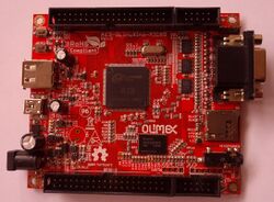
The Olimex A13-OLinuXino-Micro is a shrunk down, cheaper version of the A13-OLinuXino. The differences against the A13-OLinuXino are that it has half the ram, a single USB Host port, only u-boot and reset buttons, no RTC, battery connector, NAND or Wifi. As with all Olimex Devices this board is Open Source Hardware.
Identification
The board handily reads "A13-OLinuXino-MICRO".
Sunxi support
Current status
Supported.
Images
HW-Pack
BSP
Manual build
- For building u-boot, use the "A13-OLinuXino-Micro" target.
- The .fex file can be found in sunxi-boards as a13-olinuxinom.fex
Everything else is the same as the manual build howto.
Mainline kernel
Use the sun5i-a13-olinuxino-micro.dts device-tree file for the mainline kernel.
Tips, Tricks, Caveats
FEL mode
The U-Boot button triggers FEL mode.
VGA
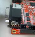
Even though the A13 does not provide DACs itself, the A13-Olinuxino has a VGA connector.
This is implemented through 3 separate DAC chips (NXP LVC244A) which are connected to the LCD0 lines. This in turn means that you cannot use an LCD and a VGA monitor at the same time, but this is ok as the A13 can only drive one display at a time anyway.
Due to the bandwidth limitations of the A13 SoC, the best resolution you can hope for is 800x600.
LCD modules
You can attach several Olimex LCD modules to the LCD connector (LCD_CON).
Expansion ports
Several expansion options are provided:
- A UEXT connector. This is meant for attaching Olimex UEXT modules.
- A 10 pin IO connector (GPIO-1).
- A 40 pin IO connector (GPIO-2).
TODO: verify that the GPIO pin-outs are a 1-1 match with the A13-OLinuXino
Adding a serial port
In the top left corner of the device, there are some pins marked UART1. The pin-out is described at the back of the board. All you have to do is connect some leads according to our UART howto.
Pictures
Take some pictures of your device, upload them, and add them here.
Also known as
There are no rebadgers for this type of device.
See also
- A13-OLinuXino: this boards big brother.
- Other Olimex hardware
- User manual
- Olimex github repository with all CAD files and schematics.


