Uploads by Apritzel
Jump to navigation
Jump to search
This special page shows all uploaded files.
| Date | Name | Thumbnail | Size | Description | Versions |
|---|---|---|---|---|---|
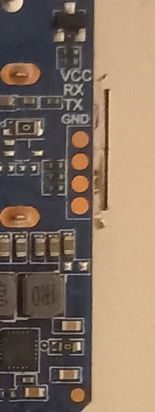
| 01:17, 24 March 2024 | Tanix tx1 uart.jpg (file) |  |
28 KB | Tanix TX1 UART pads, lower PCB side, under USB connector | 1 |
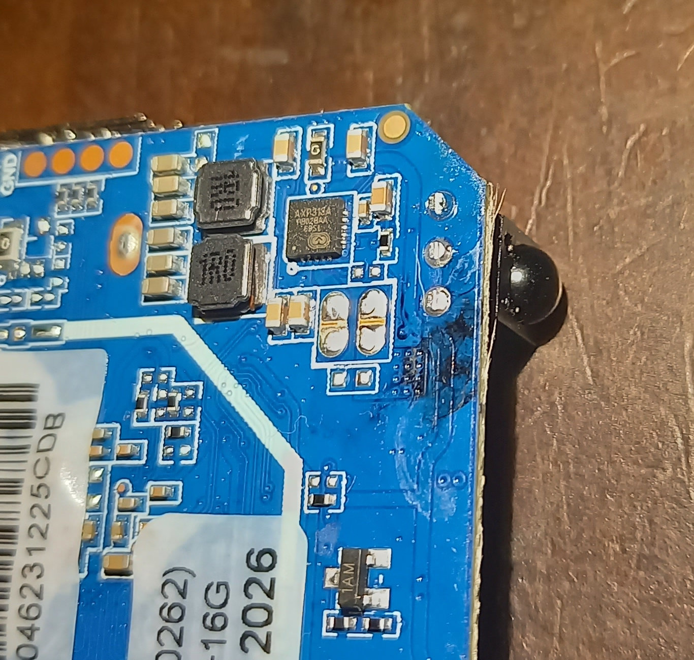
| 01:16, 24 March 2024 | Tanix tx1 pcb pmic.jpg (file) |  |
399 KB | Tanix TX1 PCB lower side, PMIC detail | 1 |
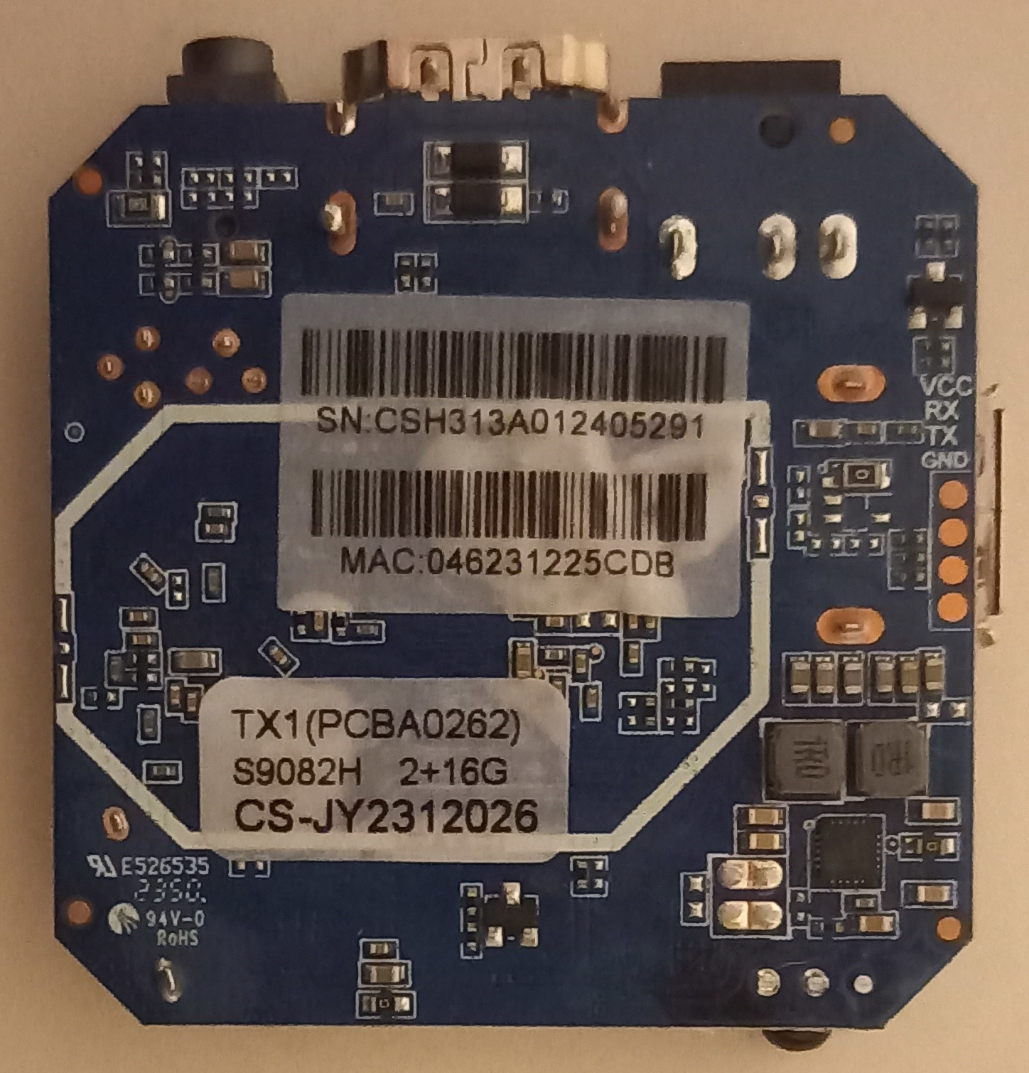
| 01:16, 24 March 2024 | Tanix tx1 pcb bottom.jpg (file) |  |
358 KB | Tanix TX1 PCB bottom view, UART pads to the right, PMIC lower right corner | 1 |
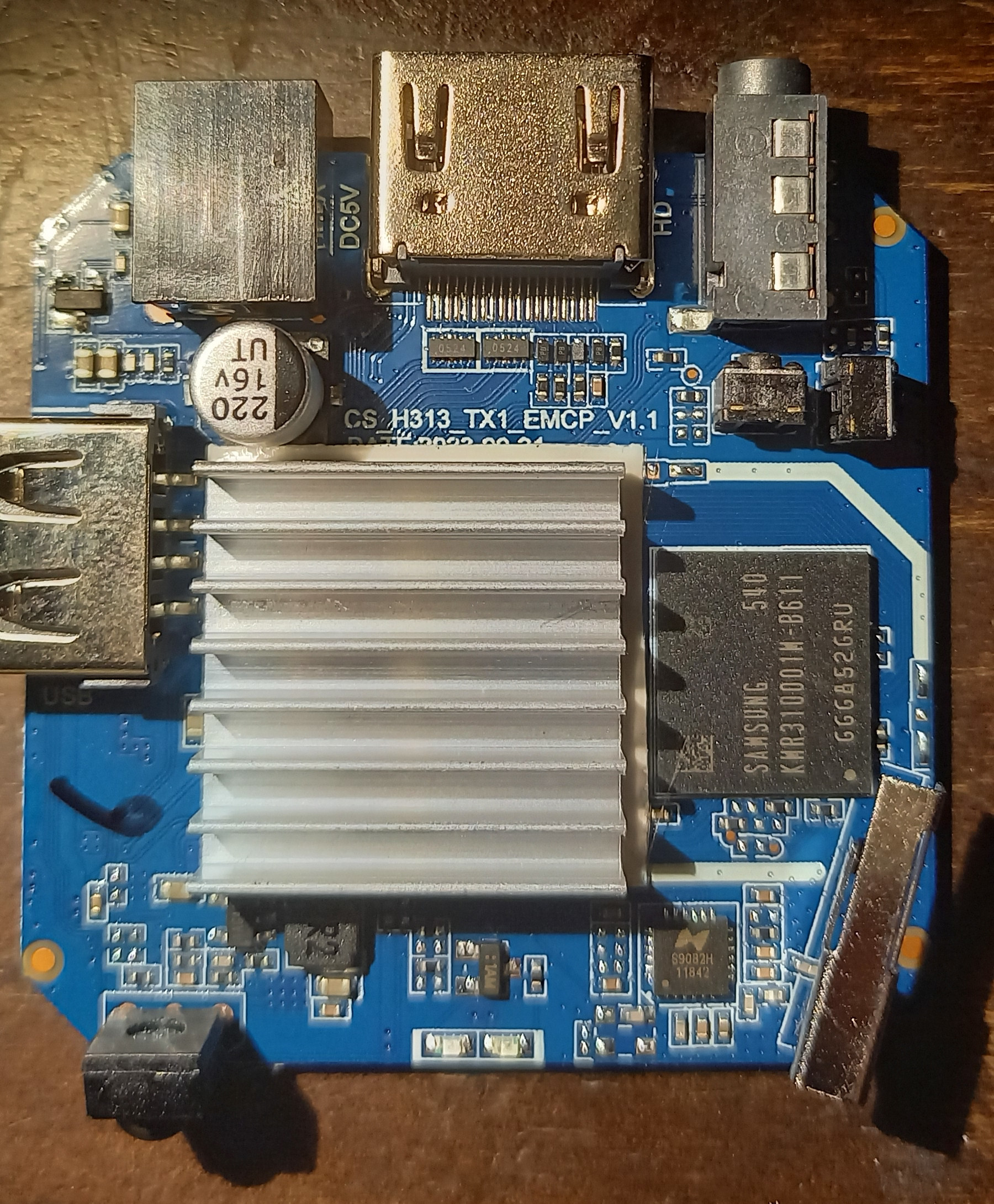
| 01:15, 24 March 2024 | Tanix tx1 pcb.jpg (file) |  |
975 KB | Tanix TX1 PCB top view, with combined eMMC/DRAM chip and WiFi chip, SoC under the heat spreader | 1 |
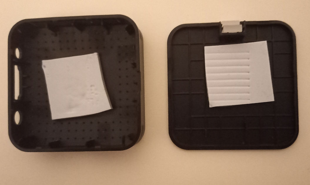
| 01:14, 24 March 2024 | Tanix tx1 shells.jpg (file) |  |
58 KB | Tanix TX1 case shells, with sticky heat spreading material | 1 |
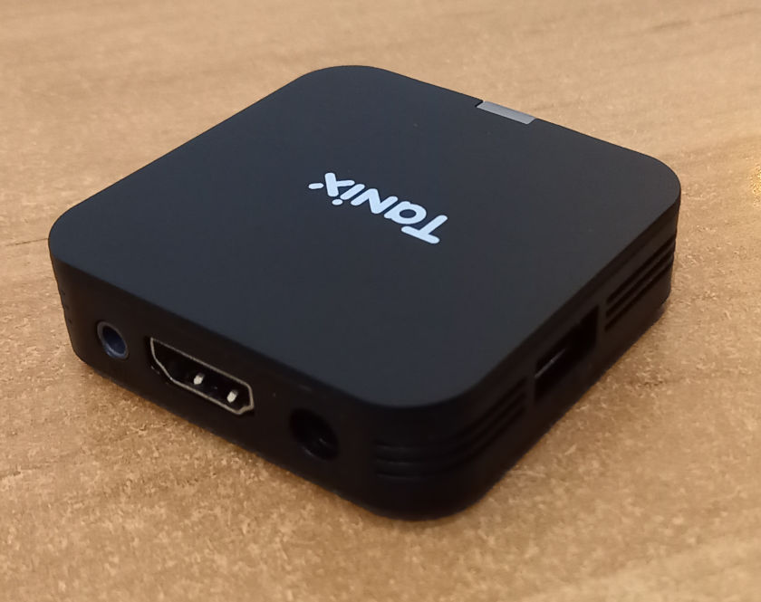
| 01:13, 24 March 2024 | Tanix tx1 rear.jpg (file) |  |
54 KB | Tanix TX1 rear view | 1 |
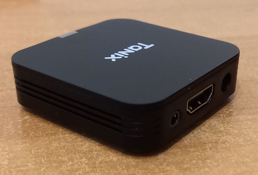
| 01:13, 24 March 2024 | Tanix tx1 ports.jpg (file) |  |
61 KB | Tanix TX1 ports: A/V, HDMI, power, USB | 1 |
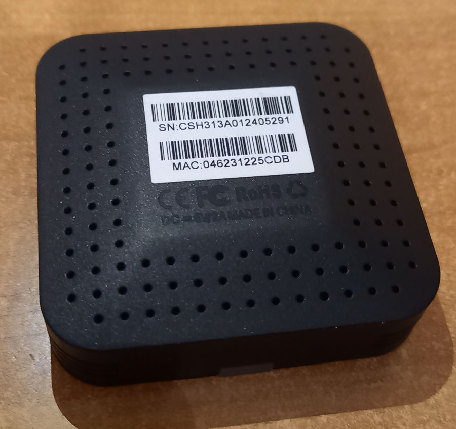
| 01:12, 24 March 2024 | Tanix tx1 bottom.jpg (file) |  |
89 KB | Tanix TX1 bottom view, no device specific label | 1 |
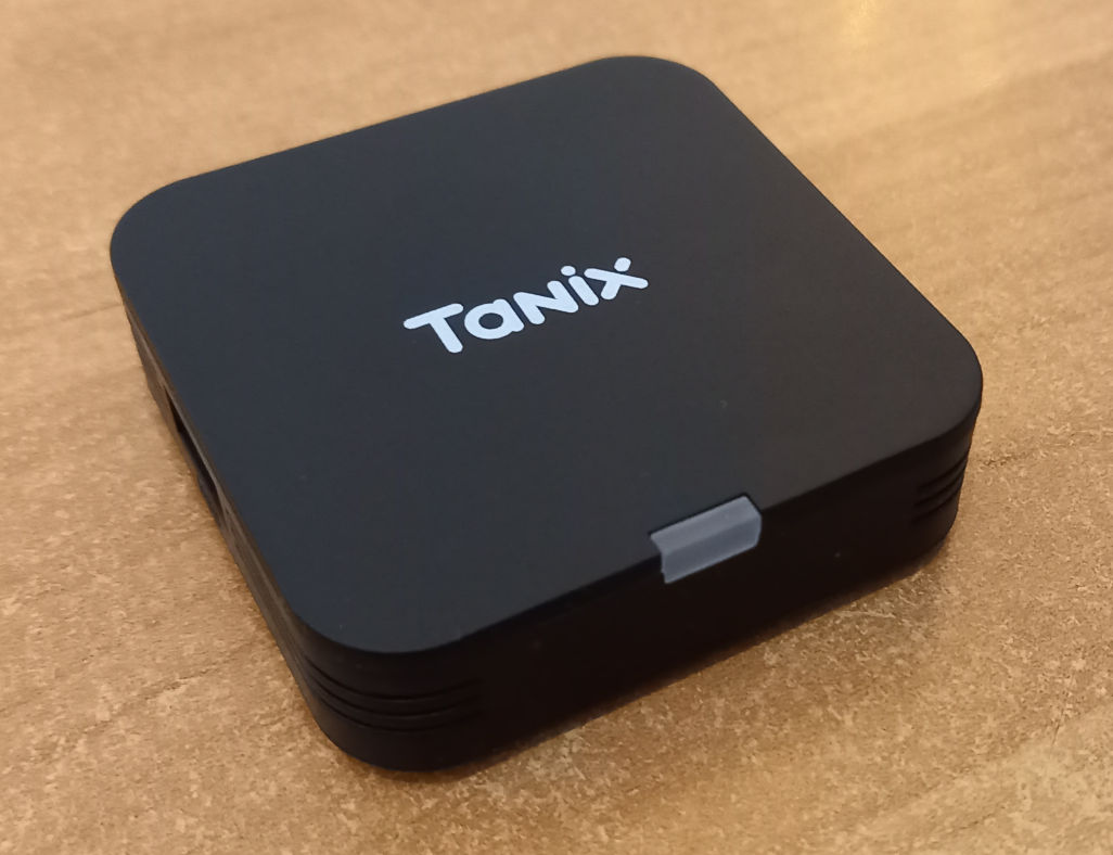
| 01:12, 24 March 2024 | Tanix tx1.jpg (file) |  |
83 KB | Tanix TX1 TV box | 1 |
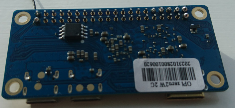
| 00:28, 29 February 2024 | Opi zero2w bottom.jpg (file) |  |
70 KB | Orange Pi Zero 2W, bottom view | 1 |
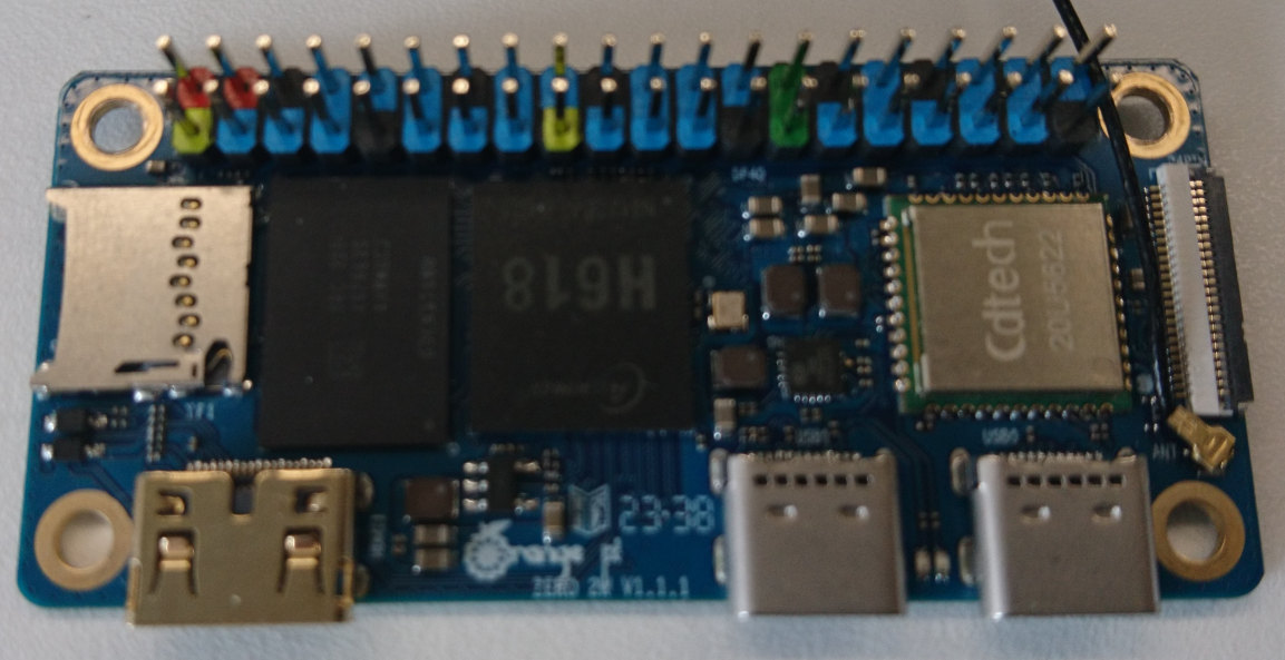
| 00:28, 29 February 2024 | Opi zero2w top.jpg (file) |  |
126 KB | Orange Pi Zero 2W, top of the PCB | 1 |
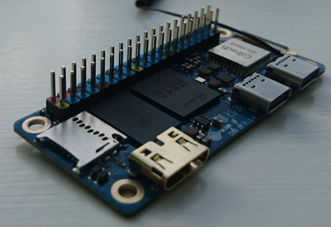
| 00:28, 29 February 2024 | Opi zero2w.jpg (file) |  |
121 KB | Orange Pi Zero 2W board, with headers | 1 |
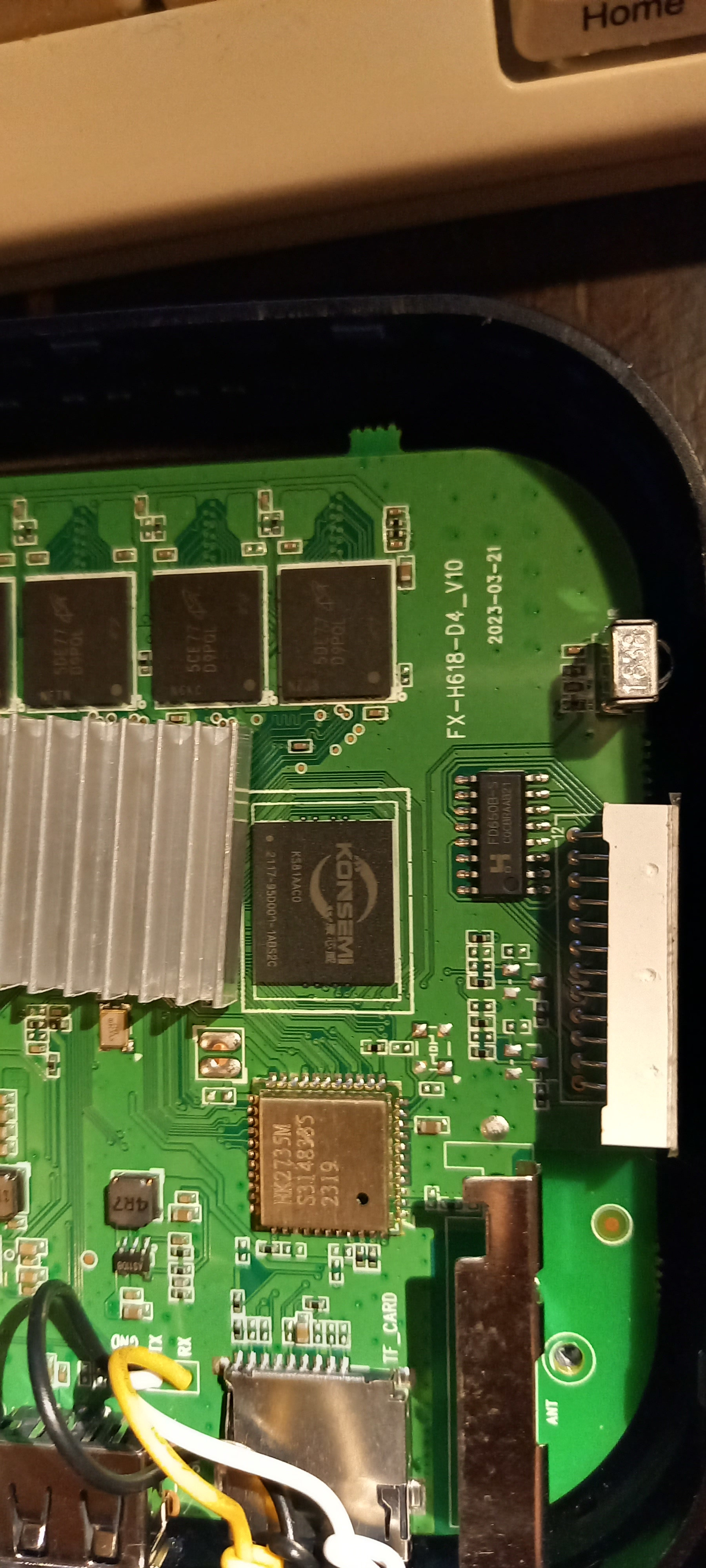
| 22:33, 25 November 2023 | Transpeed 8k pcb wifi emmc.jpg (file) | 951 KB | Transpeed 8K618-T PCB close up view, with the eMMC and WiFi chip | 1 | |
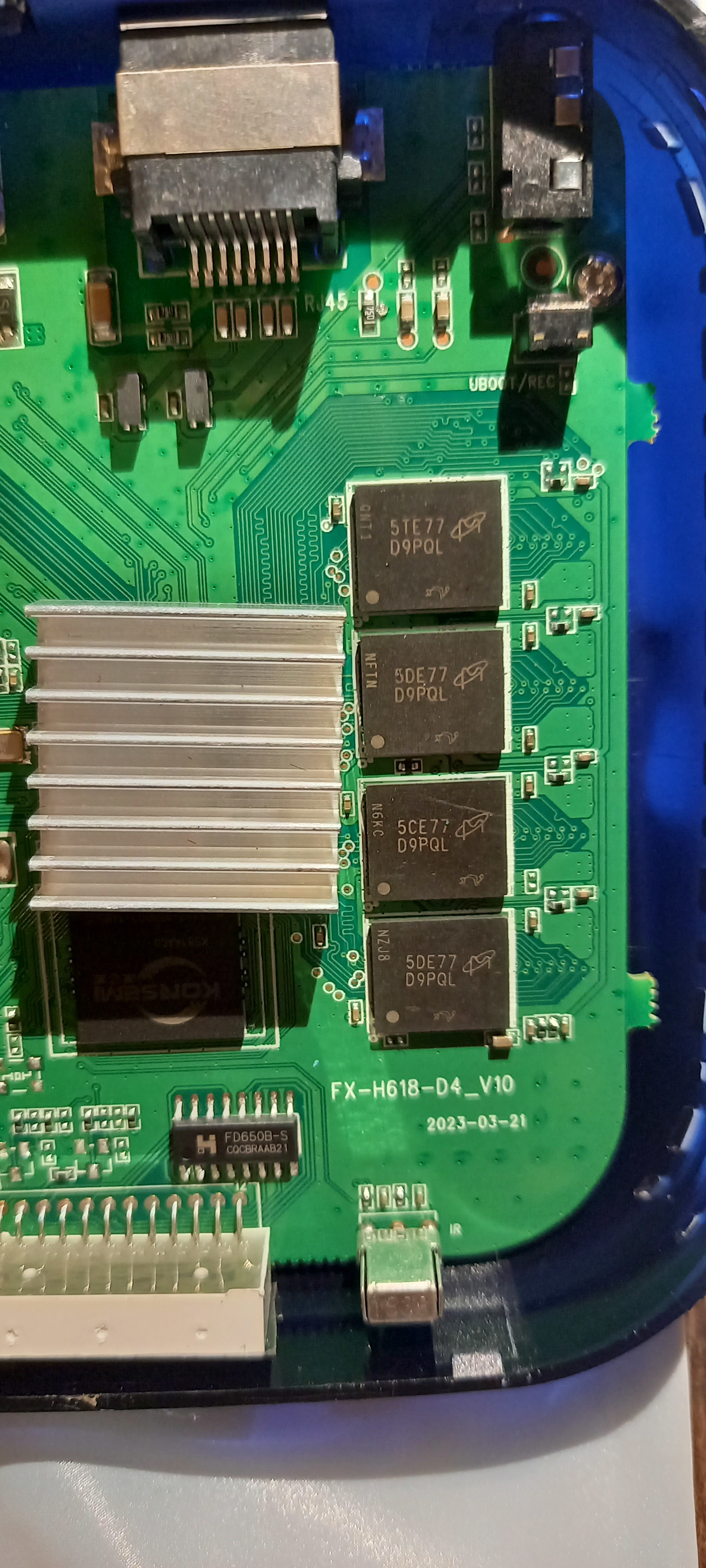
| 22:32, 25 November 2023 | Transpeed 8k pcb dram.jpg (file) | 1.09 MB | Transpeed 8K618-T PCB close up view of the DRAM chip, with readable labels. The chip at the bottom is the display driver for the four-digit 7 segment LED display. | 1 | |
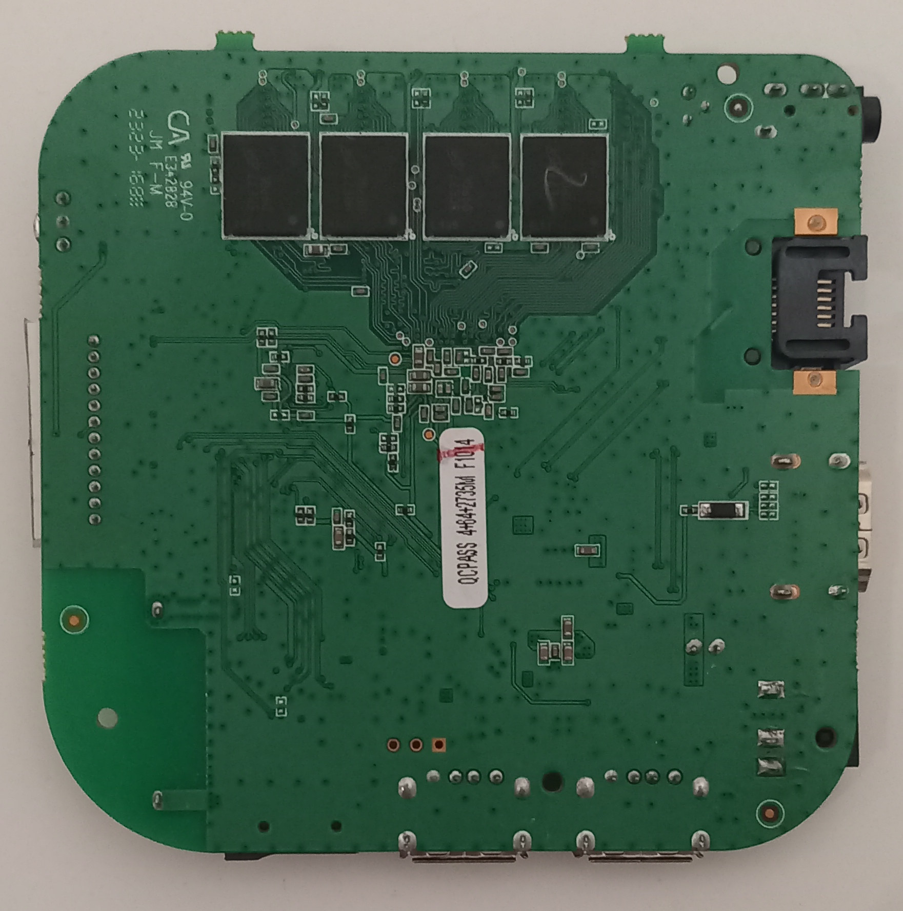
| 22:31, 25 November 2023 | Transpeed 8k pcb bottom.jpg (file) | 416 KB | Transpeed 8K618-T PCB bottom view, with the four remaining DRAM chips | 1 | |
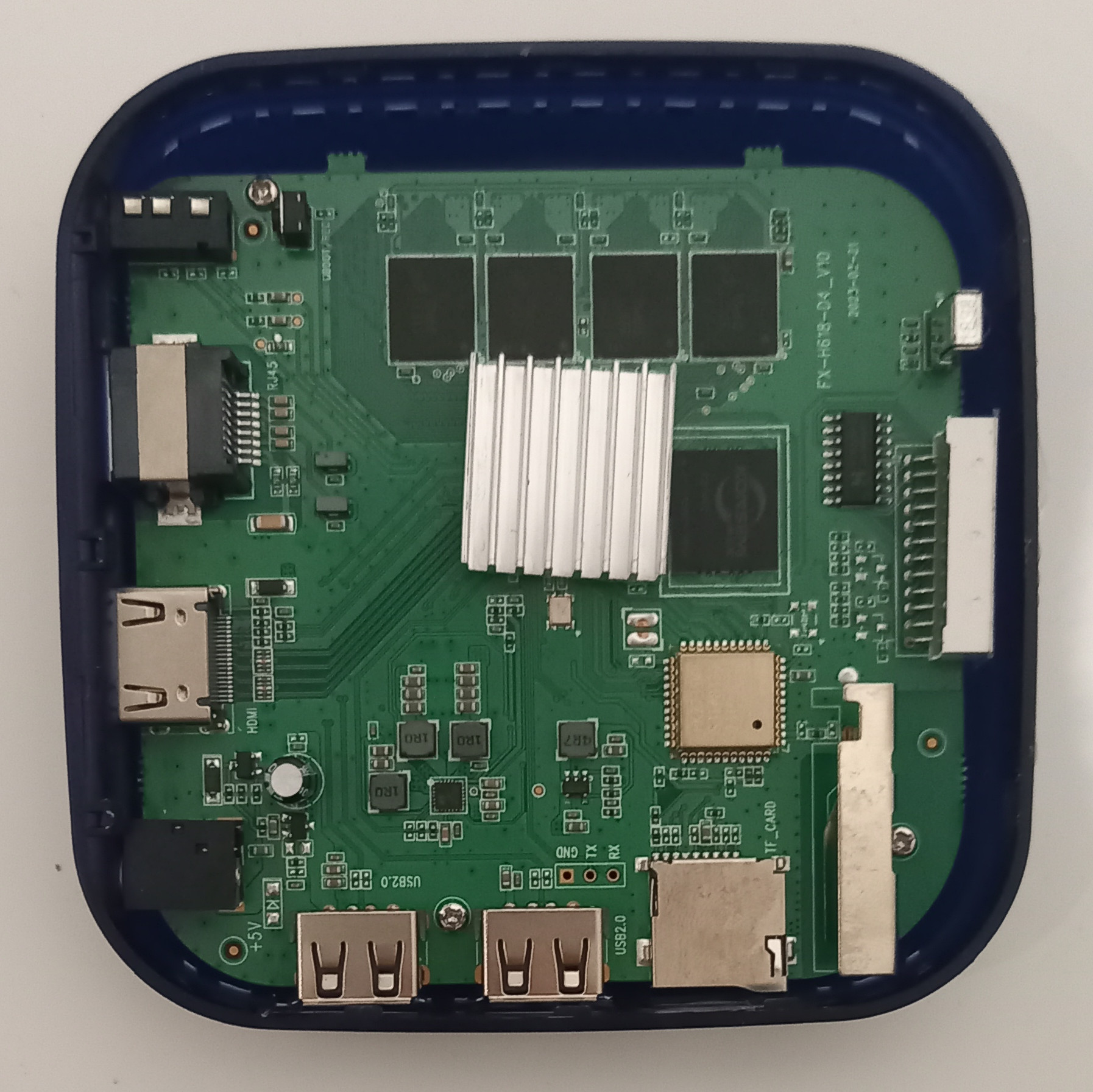
| 22:27, 25 November 2023 | Transpeed 8k pcb top.jpg (file) | 543 KB | Transpeed 8K618-T PCB top view, with 4 of the 8 DRAM chip at the top, the eMMC chip next to the SoC (under the heatsink), and the metal covered WiFi chip, The metal contraption at the lower right is an antenna. | 1 | |
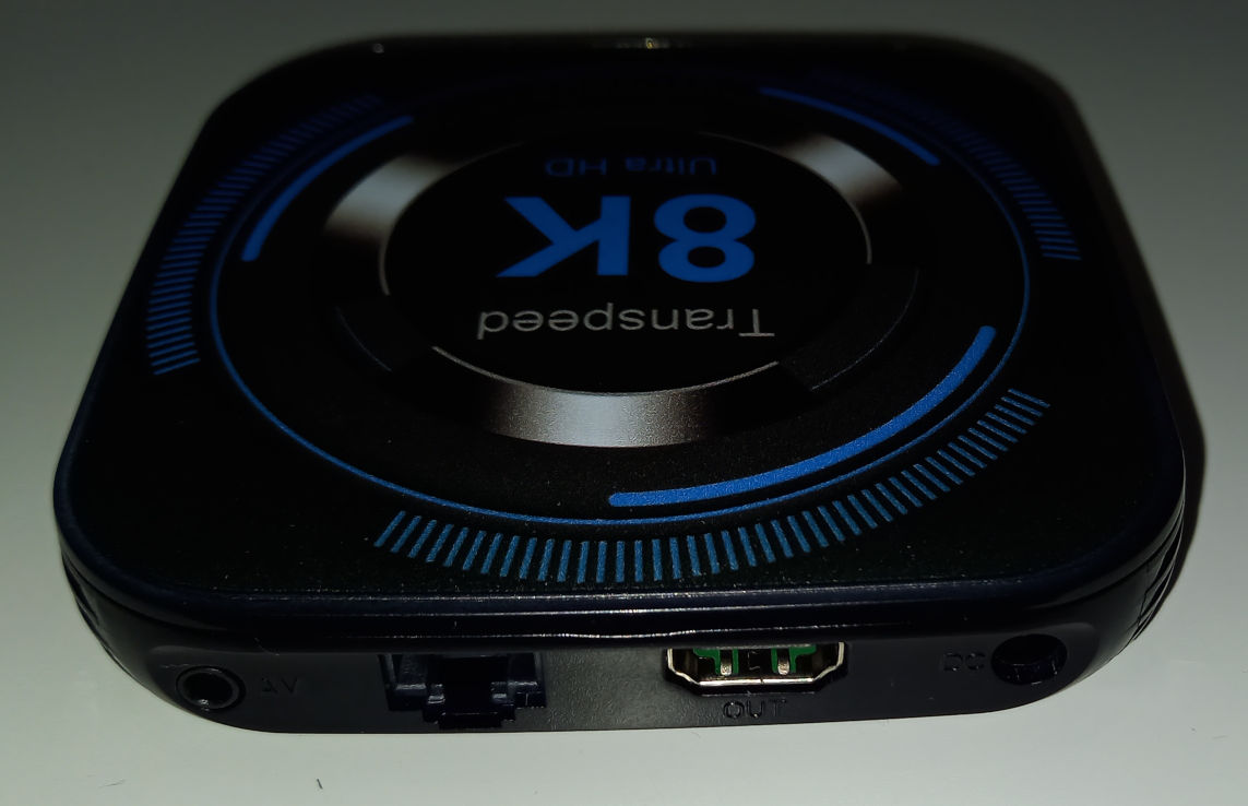
| 22:25, 25 November 2023 | Transpeed 8k rear.jpg (file) | 79 KB | Transpeed 8K618-T rear side, with AV socket, Ethernet, HDMI and power socket | 1 | |
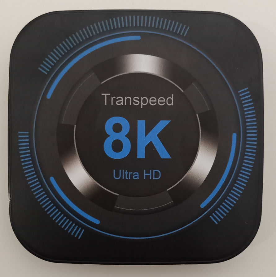
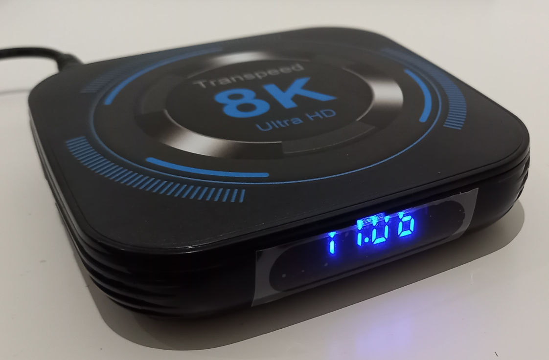
| 22:25, 25 November 2023 | Transpeed 8k top.jpg (file) | 92 KB | Transpeed 8K618-T top, the artwork is a label, you can feel a ring underneath, probably used on other designs | 1 | |
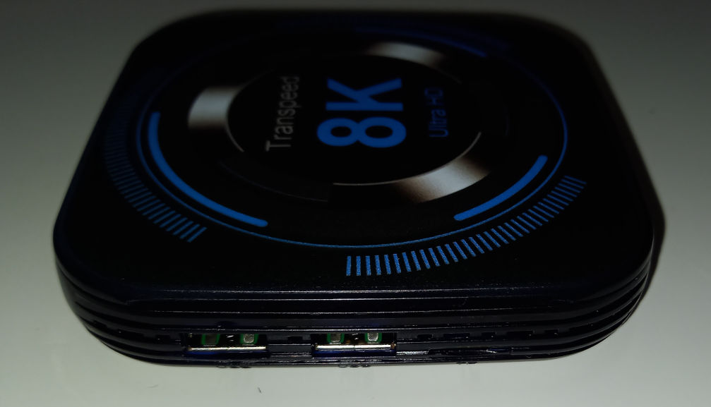
| 22:23, 25 November 2023 | Transpeed 8k side.jpg (file) | 54 KB | Transpeed 8K618-T side view: two USB 2.0 sockets, microSD card slot | 1 | |
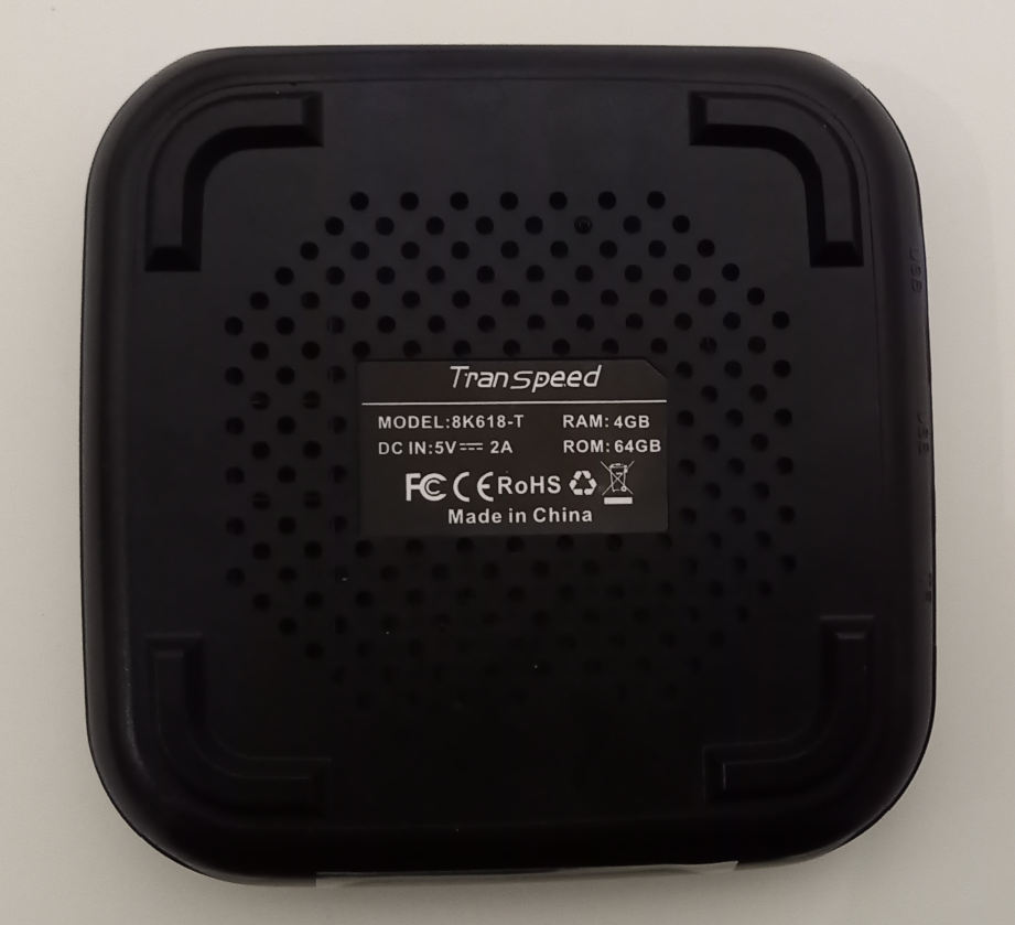
| 22:23, 25 November 2023 | Transpeed 8k bottom.jpg (file) | 53 KB | Transpeed 8K618-T bottom view | 1 | |
| 20:10, 25 November 2023 | Transpeed 8k front.jpg (file) | 68 KB | Transpeed 8K618-T front view | 1 | |
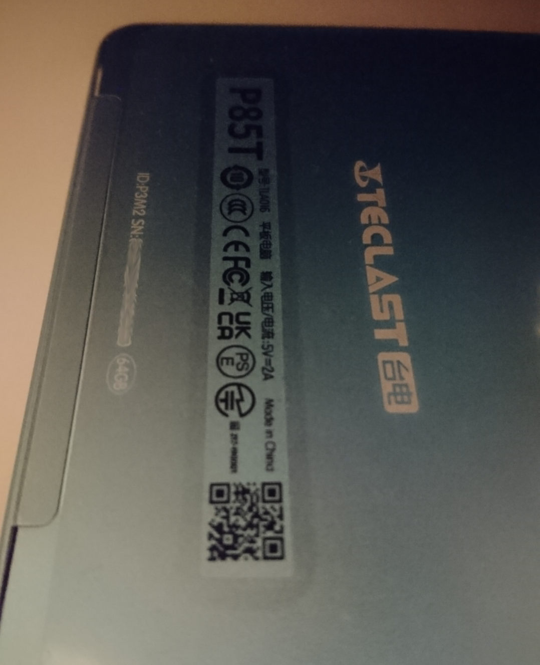
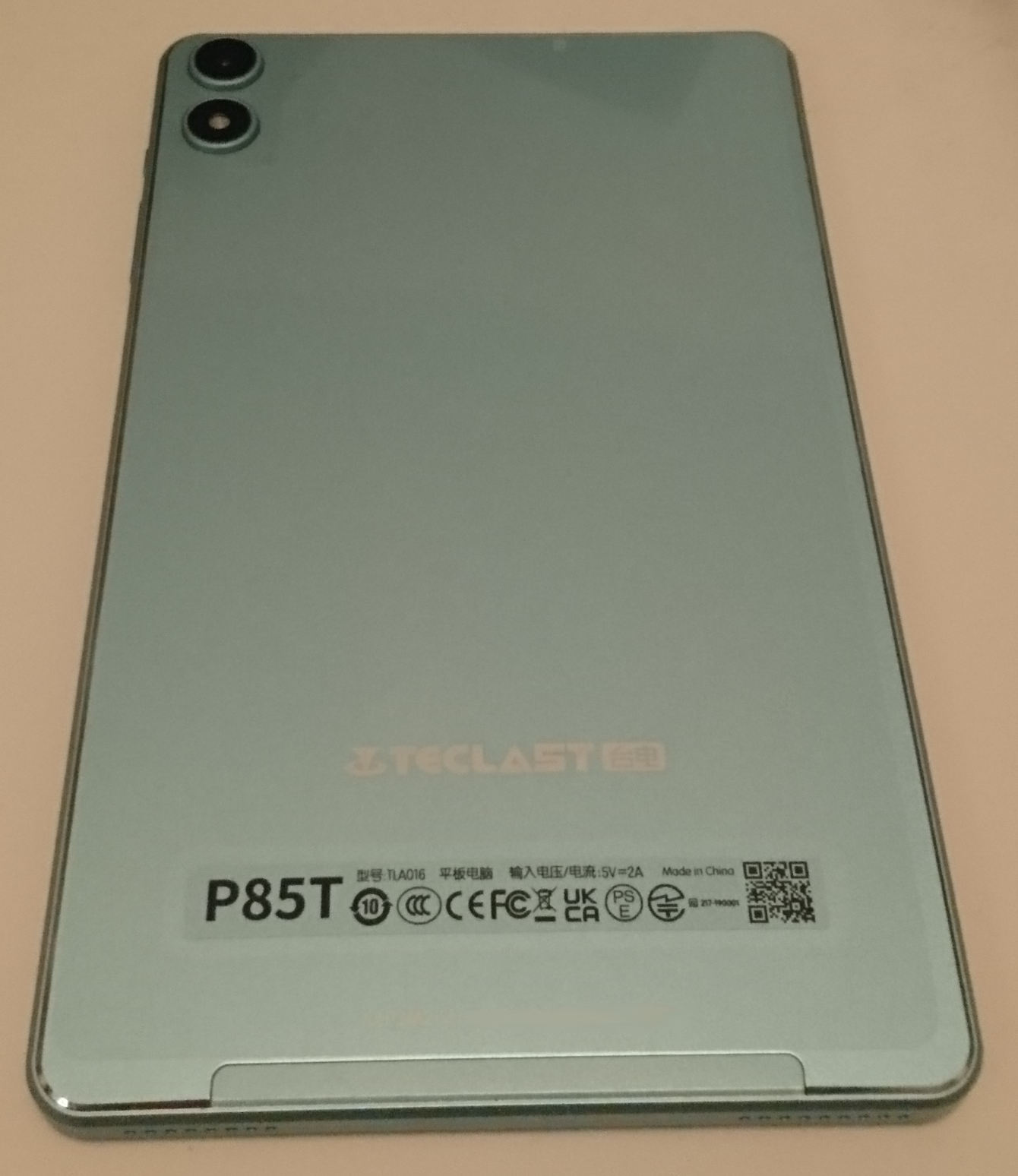
| 22:59, 5 November 2023 | Teclast p85t label.jpg (file) |  |
101 KB | Teclast P85T label at the back | 1 |
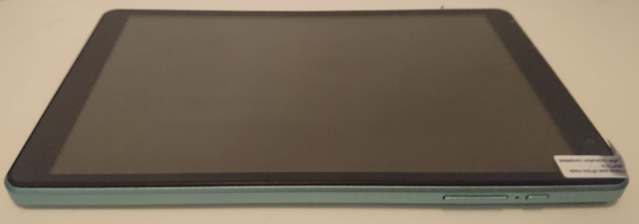
| 22:58, 5 November 2023 | Teclast p85t top.jpg (file) |  |
37 KB | Teclast P85T top view: microSD and USB-C | 1 |
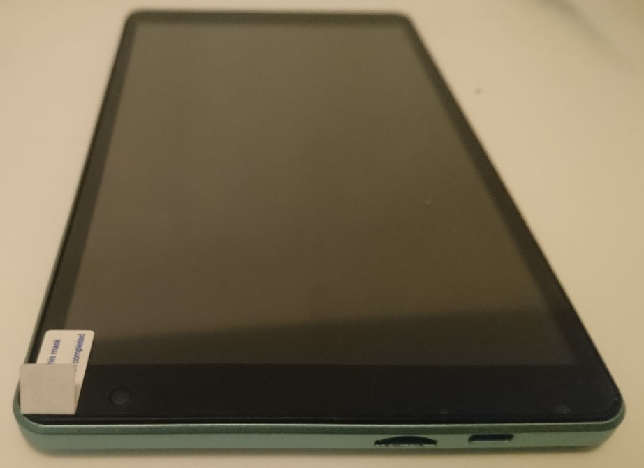
| 22:58, 5 November 2023 | Teclast p85t side.jpg (file) |  |
37 KB | Teclast P85T side view, volume buttons, reset hole, power button | 1 |
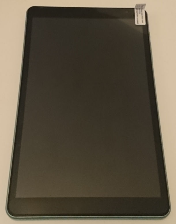
| 22:57, 5 November 2023 | Teclast p85t back.jpg (file) |  |
123 KB | Teclast P85T back view | 1 |
| 22:56, 5 November 2023 | Teclast p85t front.jpg (file) |  |
31 KB | Teclast P85T front view | 1 |
| 22:02, 5 November 2023 | A523 Brief V1.1.pdf (file) | 1.09 MB | Allwinner A523 product brief | 1 | |
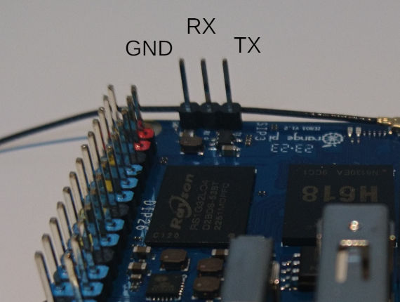
| 23:48, 30 July 2023 | OPi Zero3 UART.jpg (file) |  |
41 KB | Orange Pi Zero 3, UART0 pins with labels | 1 |
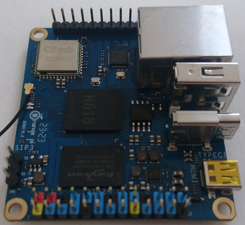
| 23:29, 30 July 2023 | OPi Zero3 top.jpg (file) |  |
113 KB | Orange Pi Zero 3, top view | 1 |
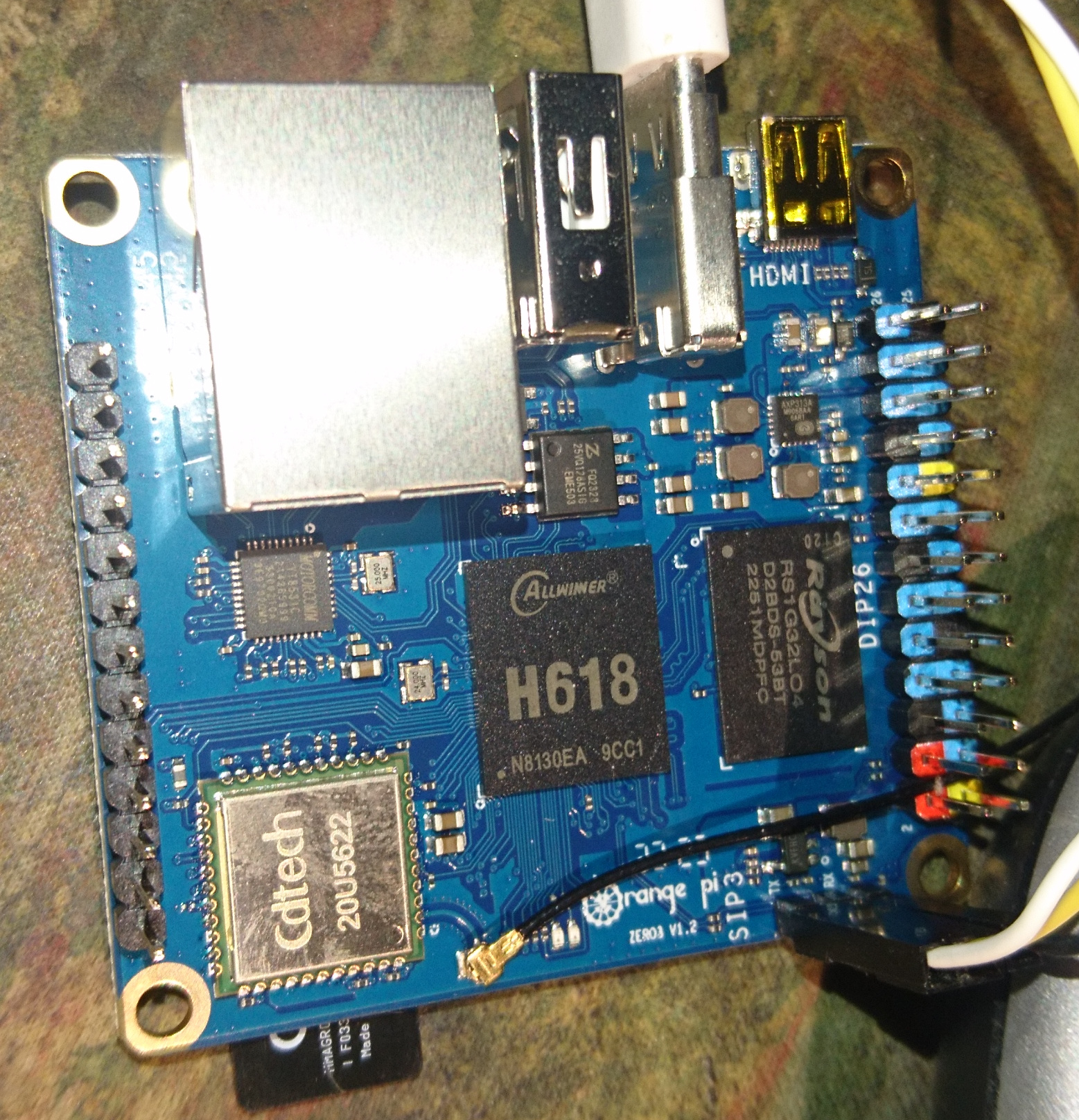
| 23:28, 30 July 2023 | OPi Zero3 chips.jpg (file) |  |
1 MB | Orange Pi Zero 3, detailed view with readable chip labels | 1 |
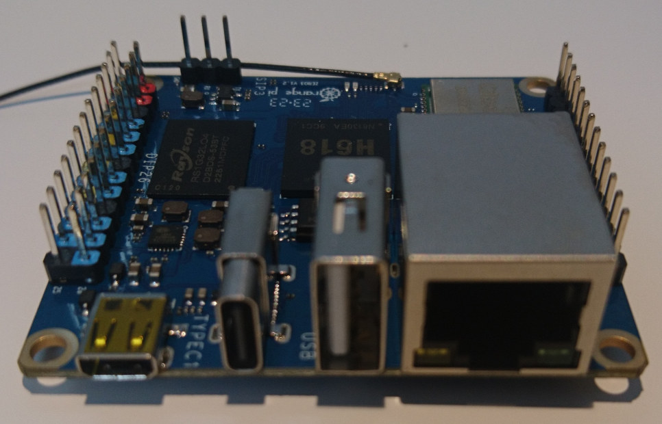
| 23:27, 30 July 2023 | OPi Zero3 connectors.jpg (file) |  |
110 KB | Orange Pi Zero 3 board, connector side view | 1 |
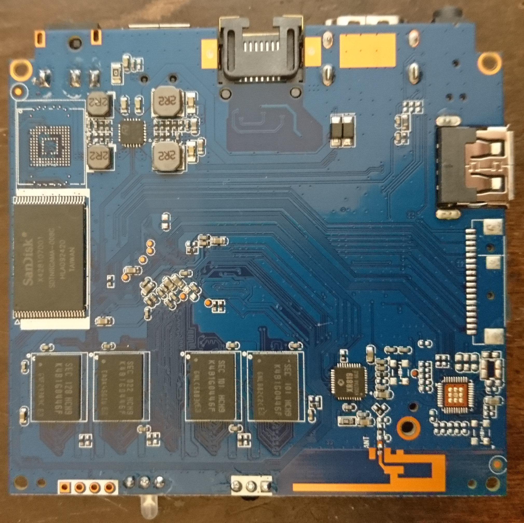
| 01:08, 23 November 2022 | Sunvell r69 blue bottom.jpg (file) |  |
870 KB | Blue (later) PCB version, bottom side | 1 |
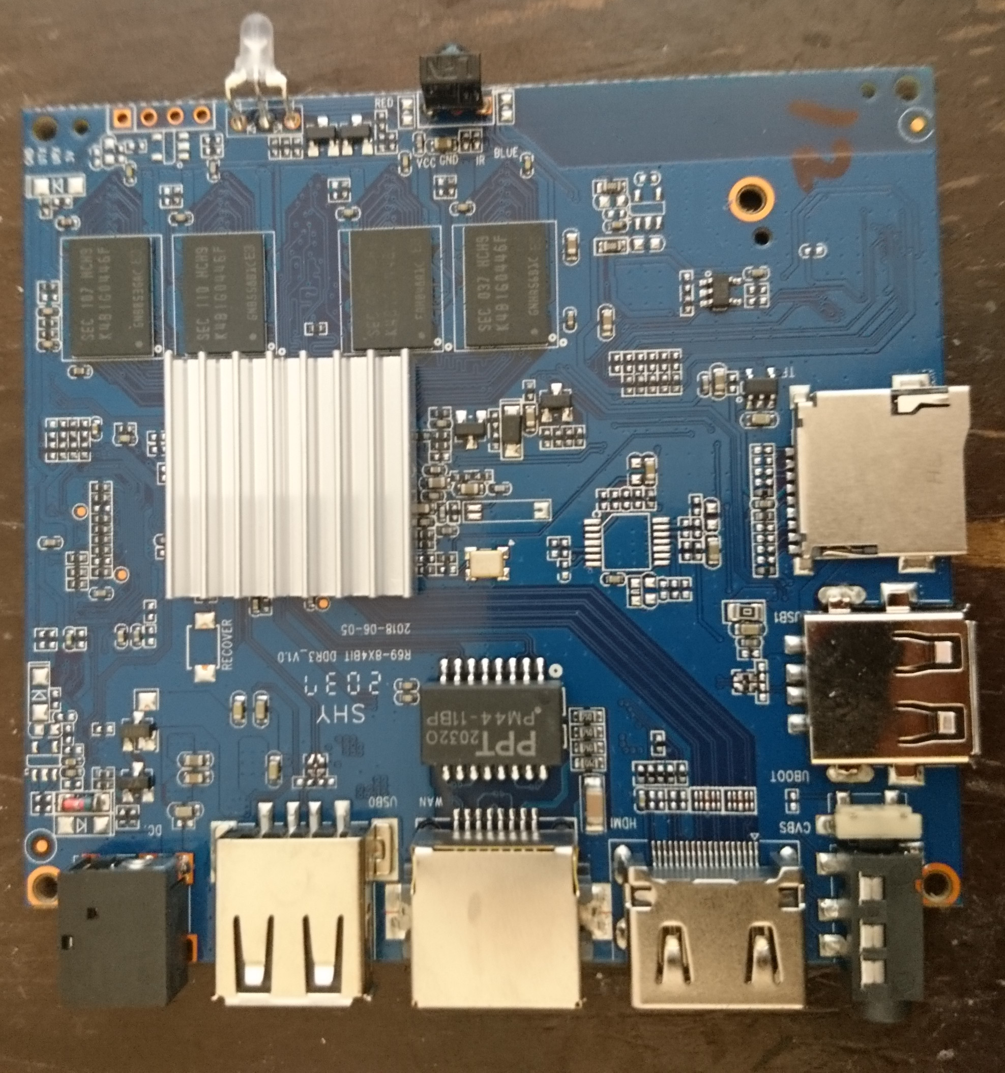
| 01:06, 23 November 2022 | Sunvell r69 blue top.jpg (file) |  |
911 KB | Blue (later) PCB version, top side | 1 |
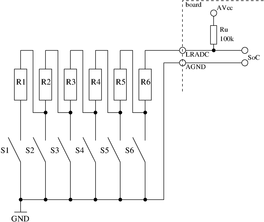
| 23:29, 7 November 2022 | LRADC network.png (file) |  |
7 KB | typical usage to connect six buttons to the LRADC | 1 |
| 00:29, 26 October 2022 | CherryPi-F1C200S.pdf (file) | 118 KB | Lctech Pi F1C200s schematic | 1 | |
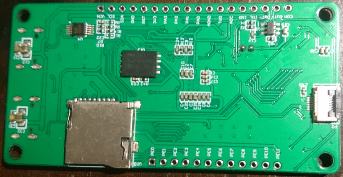
| 00:25, 26 October 2022 | Lctech Pi F1C200s bottom.JPG (file) |  |
124 KB | 1 | |
| 00:24, 26 October 2022 | Lctech Pi F1C200s USB-C.JPG (file) |  |
104 KB | 1 | |
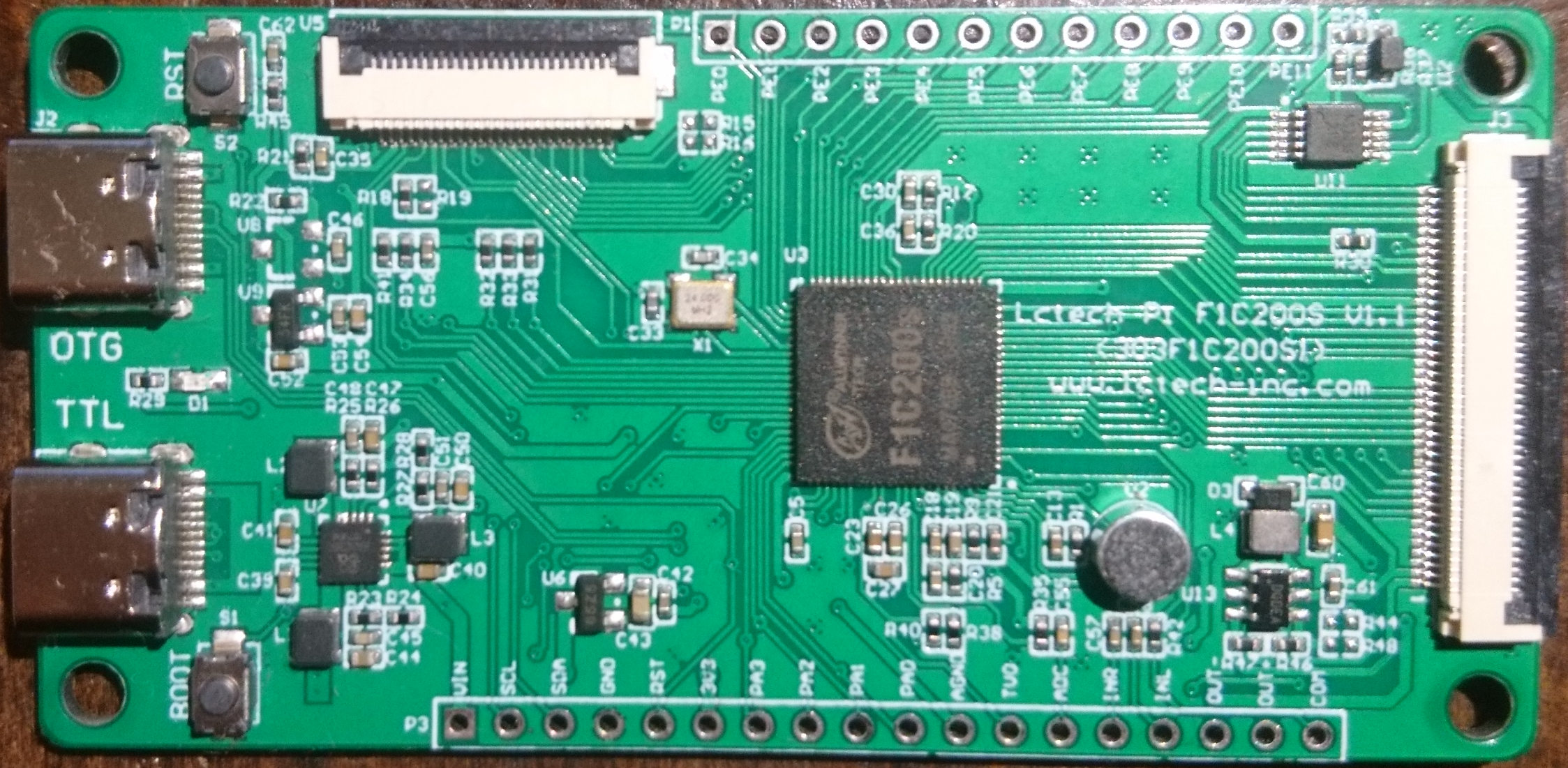
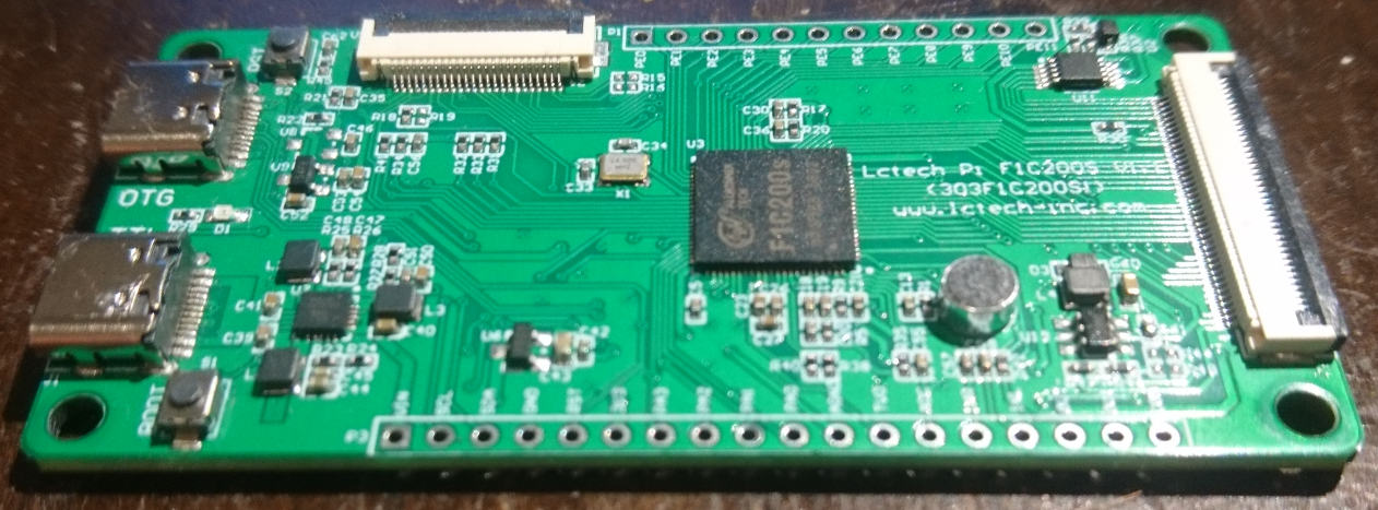
| 00:24, 26 October 2022 | Lctech Pi F1C200s top.jpg (file) |  |
551 KB | 1 | |
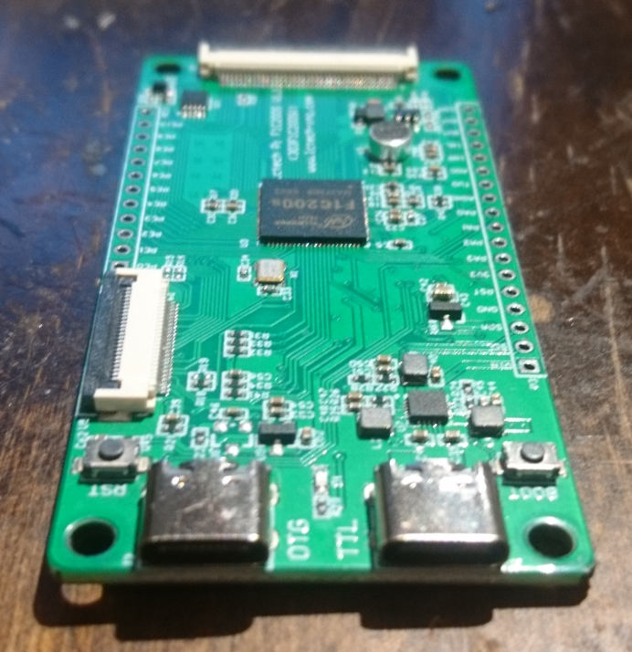
| 00:24, 26 October 2022 | Lctech Pi F1C200s side.jpg (file) |  |
132 KB | Lctech Pi F1C200s side view | 1 |
| 17:43, 18 June 2022 | BPi M2M side.jpg (file) |  |
576 KB | BananaPi M2M board side view (USB-OTG, power, USB host connector) | 1 |
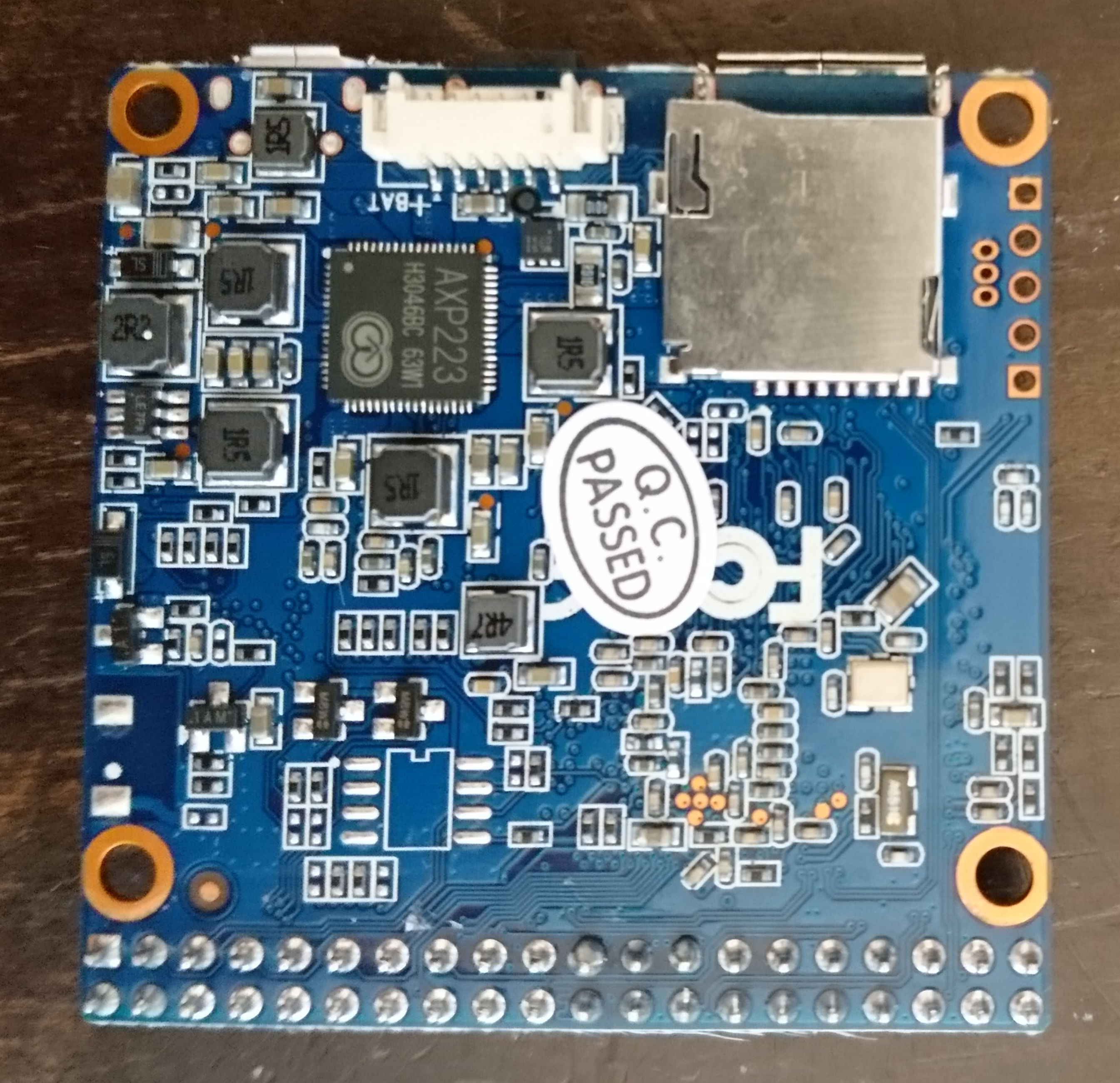
| 17:42, 18 June 2022 | BPi M2M bottom.jpg (file) |  |
916 KB | BananaPi M2M PCB bottom view | 1 |
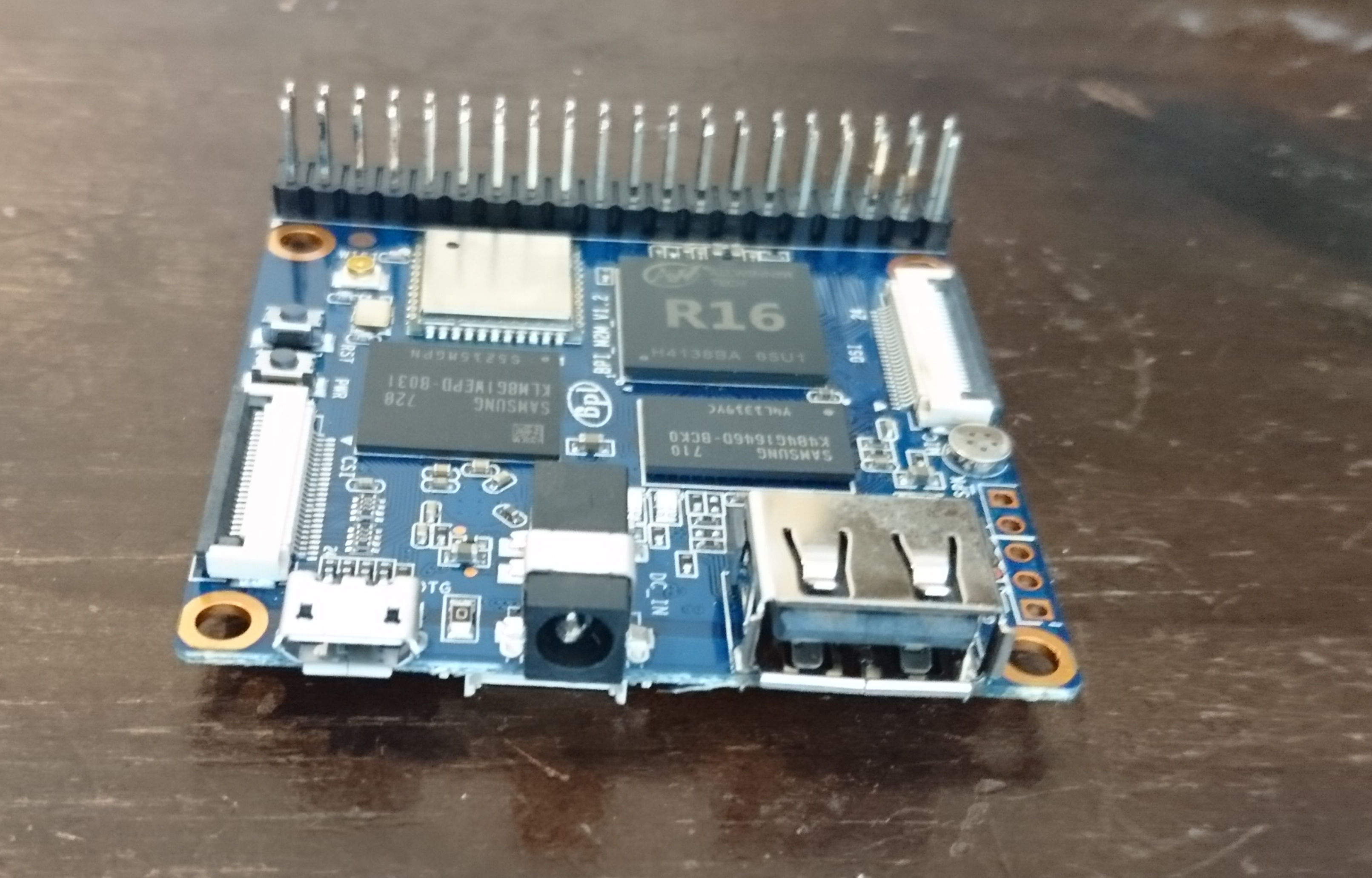
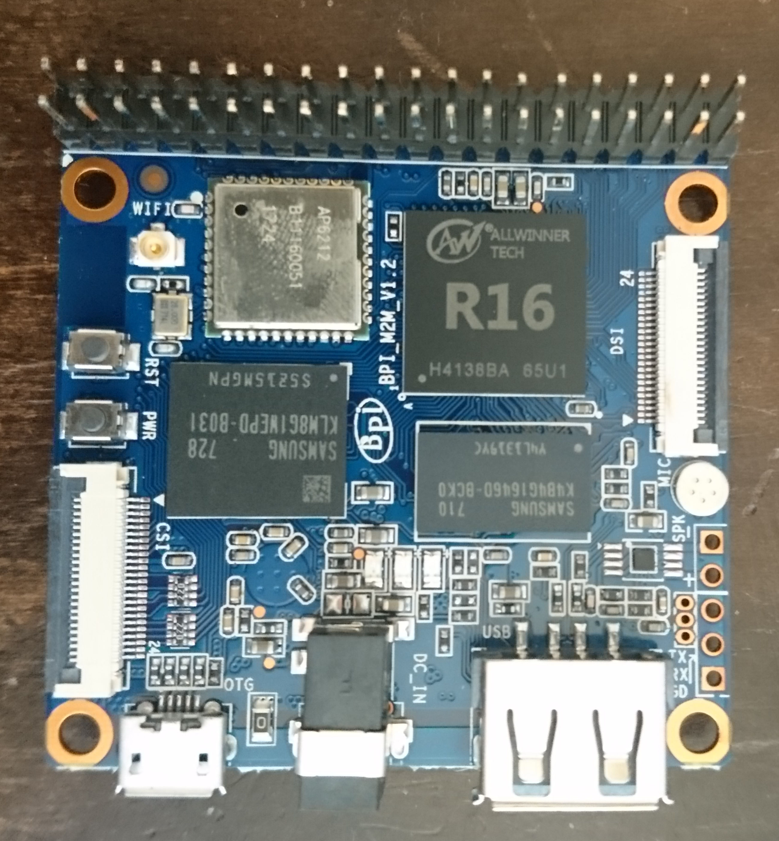
| 17:41, 18 June 2022 | BPi M2M top.jpg (file) |  |
789 KB | BananaPi M2M PCB top view | 1 |
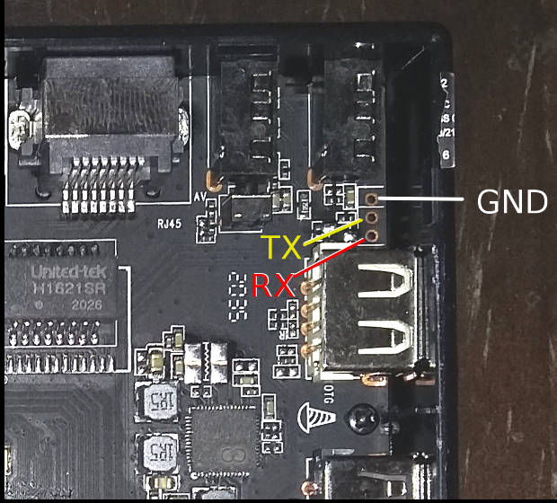
| 16:19, 25 April 2021 | X96 mate uart pads.jpg (file) |  |
81 KB | Location of X96 Mate UART pads, top right of PCB, between USB and IR connector | 1 |
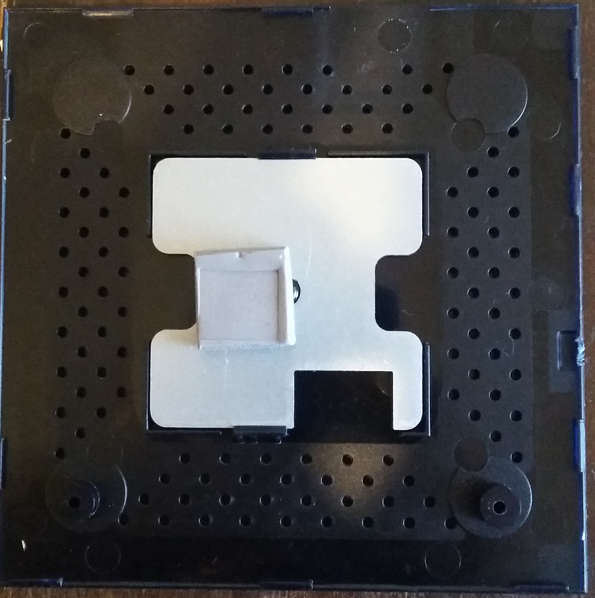
| 15:22, 25 April 2021 | X96 mate bottom plate.jpg (file) |  |
39 KB | X96 Mate bottom plate, from the inside, with heatsink and thermal paste block | 1 |
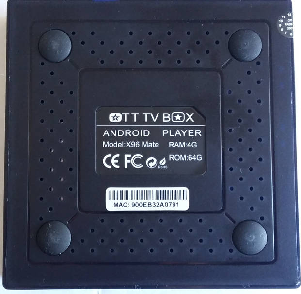
| 15:21, 25 April 2021 | X96 mate bottom.jpg (file) |  |
52 KB | X96 Mate underside | 1 |
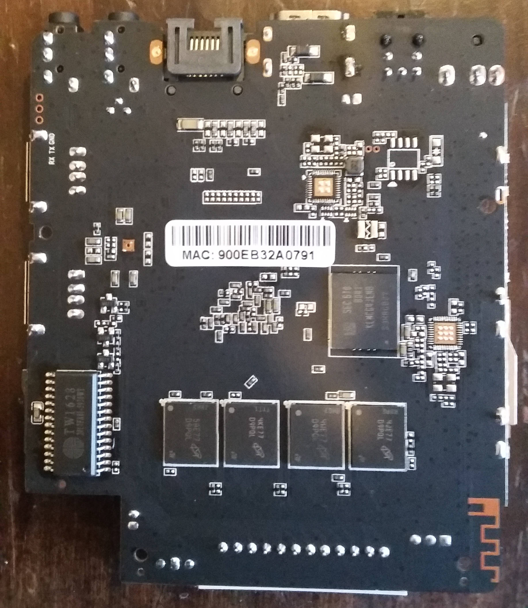
| 15:20, 25 April 2021 | X96 mate pcb bottom.jpg (file) |  |
425 KB | X96 Mate PCB view from the bottom | 1 |
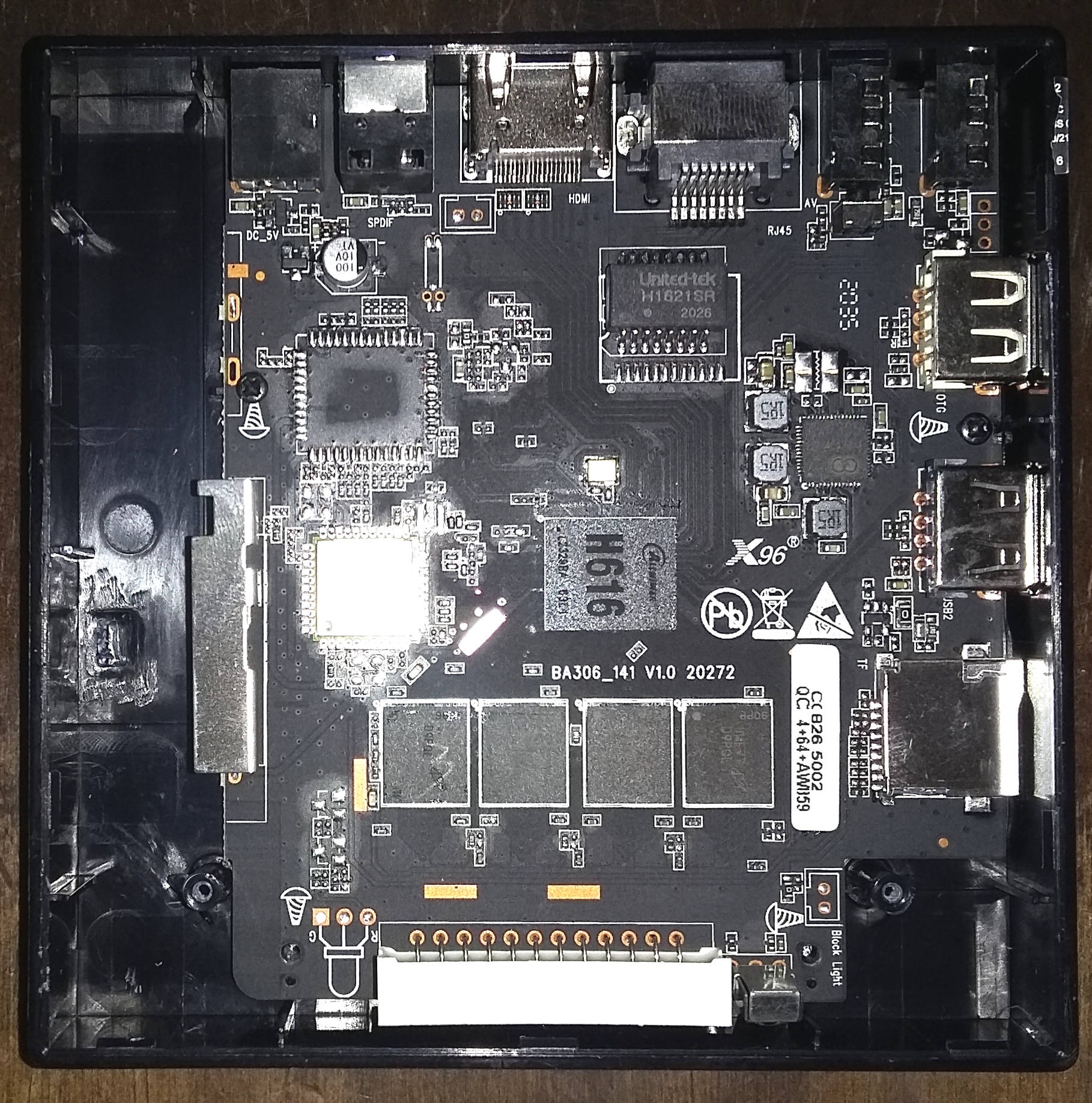
| 15:20, 25 April 2021 | X96 mate pcb top.jpg (file) |  |
561 KB | X96 Mate PCB view from the top | 1 |
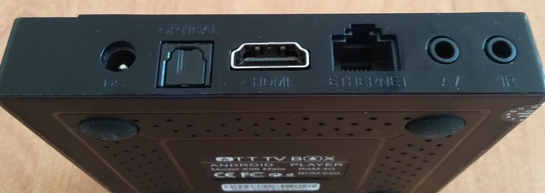
| 15:20, 25 April 2021 | X96 mate rear.jpg (file) |  |
77 KB | X96 Mate rear view with connectors | 1 |
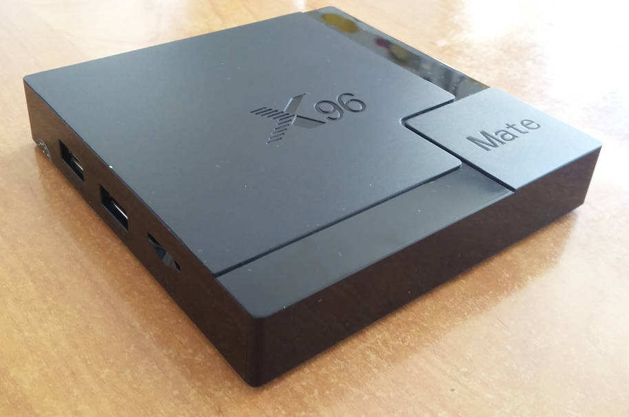
| 15:19, 25 April 2021 | X96 mate.jpg (file) |  |
50 KB | X96 Mate TV box | 1 |
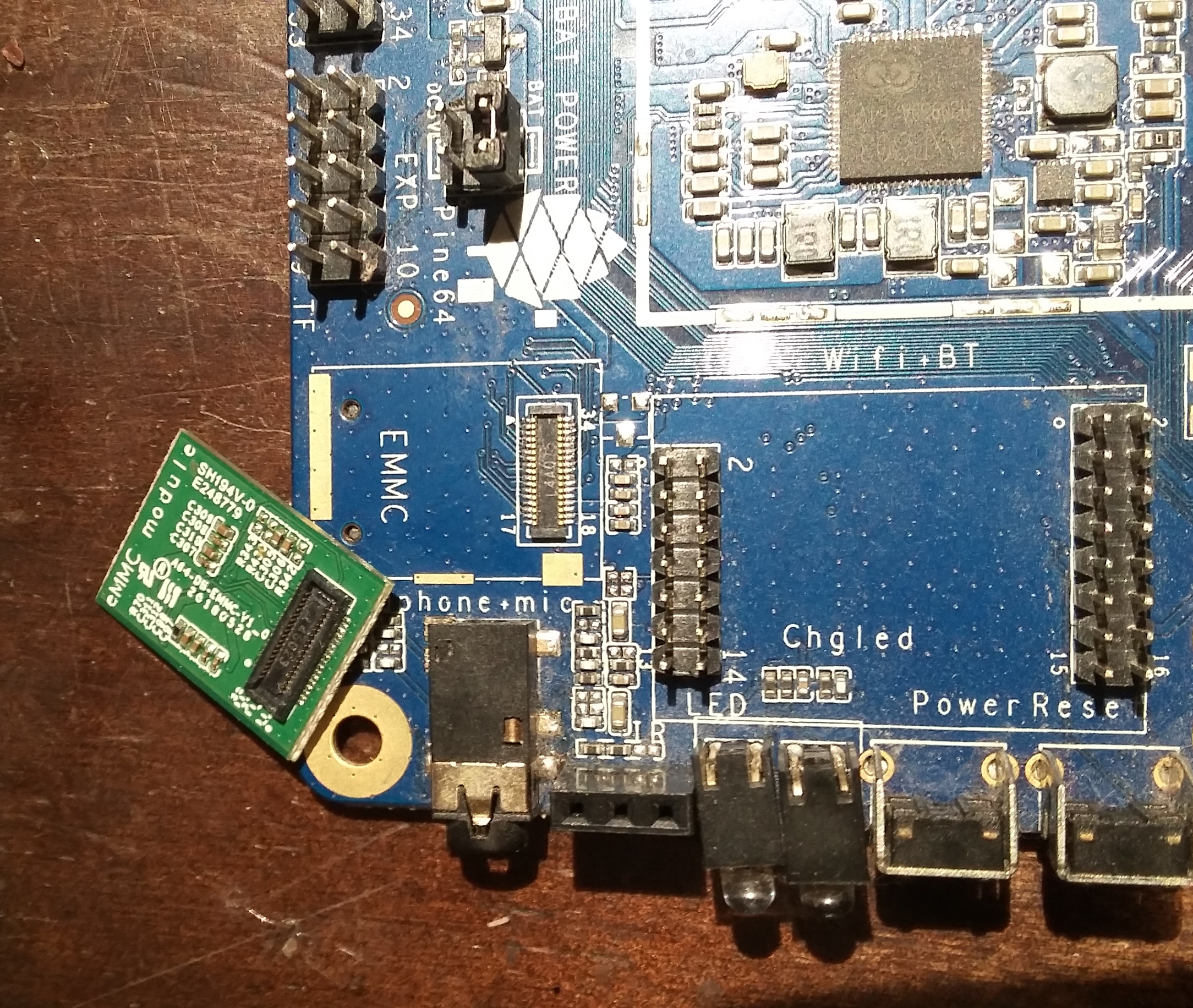
| 22:35, 16 February 2021 | EMMC-Pine64-LTS.jpg (file) |  |
1.75 MB | eMMC module (upside-down) next to the eMMC module socket on a Pine64-LTS board | 1 |