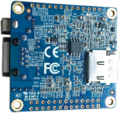
Xunlong Orange Pi Zero
| Xunlong Orange Pi Zero | |
|---|---|
 | |
| Manufacturer | OrangePi |
| Dimensions | 46mm x 48mm |
| Release Date | November 2016 |
| Website | Orange Pi Zero Product Page |
| Specifications | |
| SoC | H2+ @ 1 Ghz |
| DRAM | 256 MiB or 512 MiB DDR3 |
| Power | DC 5V DC-IN via µUSB or pin headers or PoE (optional) |
| Features | |
| Video | CVBS (on pin headers) |
| Audio | microphone, stereo line-out on pin headers |
| Network | 10/100Mbps Ethernet and XR819 Wi-Fi |
| Storage | µSD, optional SPI NOR Flash on board |
| USB | 1 USB 2.0 Host, 1 USB 2.0 OTG, 2 x USB 2.0 on pin headers |
| Other | CIR on pin headers |
| Headers | 3 pin UART, 26 + 13 pin GPIO |
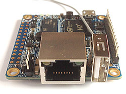
Orange Pi Zero is a small form factor board H2+ based development board produced by Xunlong.
Identification
The PCB has the following silkscreened on it:
Orange Pi Zero V1.1
The board version may vary. In Nov 2017 the most recent board version is already 1.4. It is 1.5 as of March 2019
Sunxi support
Current status
Orange Pi Zero is currently supported by both mainline U-Boot and kernels.
Manual build
U-Boot
Mainline U-Boot
For Orange Pi Zero, use the orangepi_zero_defconfig (supported since v2017.03) build target.
For Orange Pi R1, use the orangepi_r1_defconfig (supported since v2018.07) build target.
Write u-boot-sunxi-with-spl.bin to an SD card with "dd if=u-boot-sunxi-with-spl.bin of=/dev/[SD] bs=1024 seek=8 conv=notrunc"
Linux Kernel
Sunxi/Legacy Kernel
Mainline kernel
For Orange Pi Zero, use the sun8i-h2-plus-orangepi-zero.dtb (kernel 4.13+).
For Orange Pi R1, use the sun8i-h2-plus-orangepi-r1.dts
Expansion Port
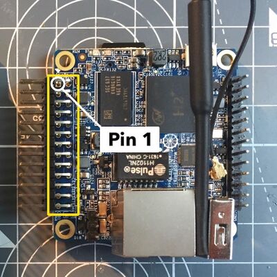
The Orange Pi Zero has a 26-pin, 0.1" unpopulated connector with several low-speed interfaces.
| 2x13 Header | |||
|---|---|---|---|
| 1 | 3.3V | 2 | 5V |
| 3 | TWI0_SDA / PA12 / GPIO12 | 4 | 5V |
| 5 | TWI0_SCK / PA11 / GPIO11 | 6 | GND |
| 7 | PWM1 / PA06 / GPIO6 | 8 | UART1_TX / PG06 / GPIO198 |
| 9 | GND | 10 | UART1_RX / PG07 / GPIO199 |
| 11 | UART2_RX / PA01 / GPIO1 | 12 | SIM_CLK/PA_EINT7 / PA07 / GPIO7 |
| 13 | UART2_TX / PA00 / GPIO0 | 14 | GND |
| 15 | UART2_CTS / PA03 / GPIO3 | 16 | TWI1-SDA / PA19 / GPIO19 |
| 17 | 3.3V | 18 | TWI1-SCK / PA18 / GPIO18 |
| 19 | SPI1_MOSI / PA15 / GPIO15 | 20 | GND |
| 21 | SPI1_MISO / PA16 / GPIO16 | 22 | UART2_RTS / PA02 / GPIO2 |
| 23 | SPI1_CLK / PA14 / GPIO14 | 24 | SPI1_CS / PA13 / GPIO13 |
| 25 | GND | 26 | SIM_DET/PA_EINT10 / PA10 / GPIO10 |
The Orange Pi Zero has another 13-pin, 0.1" header with several low-speed interfaces.
| 1x13 Header | |
|---|---|
| 1 | 5V |
| 2 | GND |
| 3 | USB-DM2 |
| 4 | USB-DP2 |
| 5 | USB-DM3 |
| 6 | USB-DP3 |
| 7 | LINEOUTR |
| 8 | LINEOUTL |
| 9 | TV-OUT |
| 10 | MIC-BIAS |
| 11 | MIC1P |
| 12 | MIC1N |
| 13 | CIR-RX |
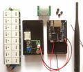
A cheap 'Expansion board' for this connector is now available exposing all interfaces (2 x USB, CIR receiver, microphone and combined AV TRRS jack) and can be ordered together with the board on Aliexpress. Attention: Expect problems when using the Expansion board to connect more USB devices when you want to power the board through the Micro USB connector (known to cause all sorts of troubles). Voltage drops affecting stability are likely to happen so better think about providing power through 5V/GND pins on the 26 pin header in this case.
Tips, Tricks, Caveats
Compatibility
The H2+ SoC used on this board seems to be a featureless H3 (no Gbit Ethernet MAC and no 4K HDMI output). Orange Pi Zero uses the same SY8113B (datasheet) voltage regulator as used on Orange Pi One/Lite that can adjust its output voltage driven by two resistors between 1.1V and 1.3V. DVFS configuration and settings for Orange Pi One/Lite work exactly the same on OPi Zero.
It should be noted that the official OS images from orangepi.org currently use broken settings leading to VDD_CPUX voltage remaining at 1.3V all the time and leading to unnecessary overheating (see here for details).
Powering the board
Orange Pi Zero unlike all other Orange Pi boards so far can be powered through the Micro USB jack (being a normal USB OTG port otherwise) or via one of the Expansion Port pin headers (using 5V/GND pins).
There is no power on/off switch or reboot switch on the board.
Passive PoE
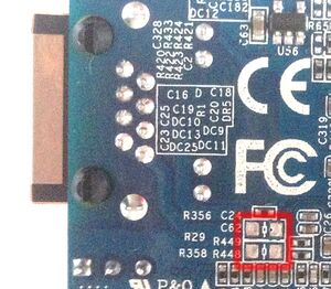
The board also provides a PoE (Power over Ethernet) option since Ethernet pins 4/5 and 7/8 are routed to solder pads (see picture on the right and below in gallery).
| Ethernet pin | Pin description | Resistor | Resistor value | Voltage |
|---|---|---|---|---|
| 4/5 | PoE+ | R29 | 0 Ohm | 5V |
| 7/8 | PoE- | R358 | 0 Ohm | GND |
By soldering zero ohm resistors to R29 and R358 passive PoE providing 5V could be used to power the board. Note that 5V won't work over large distances (greater than ~4m) since cable resistance is too high and the voltage will drop.
It's also possible to solder a buck converter between the R29 pads (PoE+ to 5V VBUS) and R358 (GND) so that passive PoE with the higher voltages (24V or 48V) can be used. The buck converter is used to step the input voltage (24/48V) down to 5V.
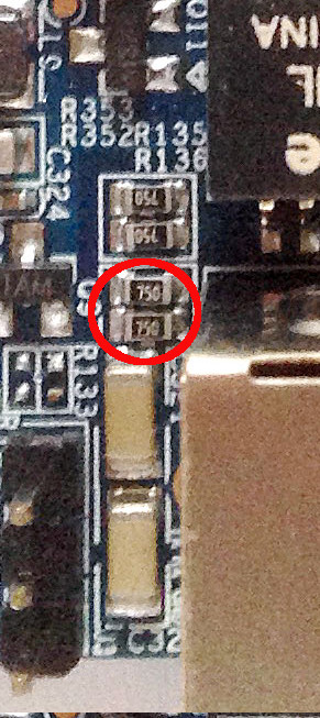
If you plan to use a buck converter at higher voltages, remove R135/R136 (75 Ohm) as they will dissipate a lot of heat and may burn out! See the picture on the right and below in the gallery for which resistors to remove.
Using Orange Pi Zero as a PoE injector
If you solder 0 Ohm resistors to R29 and R358 and power the Orange Pi Zero via Micro USB or GPIO as described in Powering the board then 5V power will also be output via the Ethernet port.
802.3af/at PoE
The Orange Pi Zero does not support 802.3af Mode A, which means it is not compliant with the PoE and PoE+ standards. PoE switches do not negotiate the output voltage, only the output power (12.95W for 802.3af and 25.5W for 802.3at).
Soldering 0 Ohm resistors to R29 and R358 will not make the Orange Pi Zero work with switches implementing PoE/PoE+
You need an 802.3af/at compliant power supply like the TP-Link TL-POE10R to use the Orange Pi Zero with a PoE switch. This is the same procedure you would use for any other non-PoE enabled device.
FEL Mode
The Orange Pi Zero runs the standard Allwinner BootROM when the SoC starts up. There are no buttons or connectors to select FEL mode so the BootROM will only enter FEL mode if a special SD card is present or if there are no valid boot options. For example if there is no boot option on the SPI NOR chip and no SD card is present then plugging the Orange Pi Zero's micro-USB port into a USB port on a PC will show up as a FEL device. Using Sunxi tools and issuing:
$ sunxi-fel ver
shows:
AWUSBFEX soc=00001680(H3) 00000001 ver=0001 44 08 scratchpad=00007e00 00000000 00000000
SPI NOR flash
Xunlong has been asked to add support for Bootable SPI flash and while Orange Pi PC 2 came already with SPI NOR flash soldered it was optional on first Orange Pi Zero production batches. Starting in mid Dec 2016 Xunlong sells the 512 MiB variant with 16 Mb (2 MB) flash pre-populated and next production batch of the 256 MiB version will have NOR flash soldered too.
Putting u-boot on SPI NOR
You can define CONFIG_SPL_SPI_FLASH_SUPPORT, CONFIG_SPI_BOOT, CONFIG_SPL_SPI_SUNXI to get SPI flash support. This build of u-boot can boot from MMC, FEL or the SPI NOR FLASH. From the same binary.
Installing from FEL boot
You can write this image to the SPI flash to boot from fel:
$ sunxi-fel -v -p spiflash-write 0 u-boot-sunxi-with-spl.bin
Installing from linux
Because u-boot can't actually interact with the flash once it's booted you need to write u-boot to it from linux. With a mainline kernel you need to enable the SPI NOR drivers in the kernel config and add a DT node something like this:
&spi0 {
        status = "okay";
        flash: m25p80@0 {
                #address-cells = <1>;
                #size-cells = <1>;
                compatible = "winbond,w25q128";
                reg = <0>;
                spi-max-frequency = <40000000>;
        };
};
This will give you /dev/mtd0 that you can use to write u-boot to the flash.
flash_erase /dev/mtd0 0 128
flashcp u-boot-sunxi-with-spl.bin /dev/mtd0
Once Linux is running you could mount a filesystem from the flash etc.
SPI NOR on older boards
Pre dec 2016 boards do not have SPI NOR Flash installed. So you need to install your own.
To put u-boot on SPI NOR you first need to solder on an SPI flash. The W25Q128FVSIG is 16 megabytes, cheap and easy to source and the correct package for the footprint on the orangepi zero PCB. Soldering it on is relatively easy. Clean the footprint with solder wick first to make it flat and be careful of all of the small SMD passives close by.
When using 2017-09 mainline u-boot with the above options enabled should produce a binary that already works out of the box. However, if you are using a SPI NOR flash from a vendor that isn't compatible with Winbond or Macronix, then you might have to enable/implement drivers for the SPI NOR flash chip that you are using.
WiFi
On OPi Zero PG10 pin seems to be used to implement WoWLAN. XR819 module contains an own ARM core and iw list when used with Allwinner's BSP driver mentions:
WoWLAN support:
    * wake up on anything (device continues operating normally)
    * wake up on disconnect
LEDs
The board has two LEDs next to DRAM:
- A red LED, connected to the PA17 pin.
- A green LED, connected to the PL10 pin.
Note: All other H3 devices currently supported connect the red led to PA15 pin so in case you want to toggle led status in u-boot pretty early OPi Zero needs special treatment.
JTAG
Connect gnd and target voltage to any of the gnd and vcc3v3-ext pins on the 2x13 expansion connector (con4). Pin 11 (uart2_rx) is TCK, pin 13 (uart2_tx) is TMS, pin 15 (uart2_cts) is TDI and pin 22 (uart2_rts) is TDO.
The JTAG sel pins that seem to be used to enable JTAG at chip power on aren't broken out but you can enable JTAG on the expansion connector once uboot has started with this command (add it to boot script and compile boot.scr again to make it permanent):
mw.l 0x01c20800 0x77223333 1
OpenOCD configuration should look something like this (based on the config from this page in Japanese):
source [find interface/ftdi/dp_busblaster_kt-link.cfg]
adapter_khz 300
transport select jtag
reset_config none
gdb_breakpoint_override hard

if { [info exists CHIPNAME] } {
   set  _CHIPNAME $CHIPNAME
} else {
   set  _CHIPNAME sun8iw7
}

if { [info exists DAP_TAPID] } {
    set _DAP_TAPID $DAP_TAPID
} else {
    set _DAP_TAPID 0x5ba00477
}

jtag newtap $_CHIPNAME dap -expected-id $_DAP_TAPID -irlen 4 -ircapture 0x01 -irmask 0x0f

set _TARGETNAME0 $_CHIPNAME.cpu0
set _TARGETNAME1 $_CHIPNAME.cpu1
set _TARGETNAME2 $_CHIPNAME.cpu2
set _TARGETNAME3 $_CHIPNAME.cpu3

target create $_TARGETNAME0 cortex_a -chain-position $_CHIPNAME.dap -coreid 0
target create $_TARGETNAME1 cortex_a -chain-position $_CHIPNAME.dap -coreid 1
target create $_TARGETNAME2 cortex_a -chain-position $_CHIPNAME.dap -coreid 2
target create $_TARGETNAME3 cortex_a -chain-position $_CHIPNAME.dap -coreid 3
target smp $_TARGETNAME0 $_TARGETNAME1 $_TARGETNAME2 $_TARGETNAME3

$_TARGETNAME0 configure -event gdb-attach {
    cortex_a dbginit
}
$_TARGETNAME1 configure -event gdb-attach {
    cortex_a dbginit
}
$_TARGETNAME2 configure -event gdb-attach {
    cortex_a dbginit
}
$_TARGETNAME3 configure -event gdb-attach {
    cortex_a dbginit
}
This is a little bit fragile but it works well enough to set breakpoints in the kernel with GDB so should be useful when debugging drivers etc.
Adding a serial port
Locating the UART
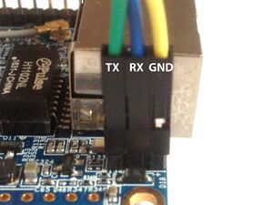
The UART pins are located next to Ethernet jack on the board. They are marked as TX, RX and GND on the PCB. Just attach some leads according to our UART Howto.
Pictures
Orange Pi Zero
Orange Pi R1
Variants
Orange Pi Zero LTS
According to CNX Software, a long term support version of the zero board will be released in the future. Shenzhen Xunlong Software claims the LTS board will have improved board design with lower power consumption and SoC temperature, along with (unspecified) long term availability.
Orange Pi R1
In August 2017 an H2+ based Orange Pi R1 has been released with 256 MB DRAM, 16 MB (128 Mb) SPI NOR flash, XR819 Wi-Fi replaced with RTL8189ETV and 2 Fast Ethernet MagJacks. One is connected to H2+ internal Fast Ethernet PHY while the other is connected to an onboard RTL8152B USB Ethernet controller attached to usb1 (the Type A receptable is missing on this board since replaced with the second Ethernet Jack). No PoE option any more.
Orange Pi Zero Plus
In October 2017 an H5 based Orange Pi Zero Plus has been released. The Plus variant differs from the original by having the H5 SoC instead of H3, gigabit ethernet support (Realtek RTL8211E), and WiFi 802.11 b/g/n provided with RTL8189FTV instead of XR819.
Also known as
See also
- Xunlong Orange Pi site
- Official Github Repository.
- Official Orange Pi Forums.
- Orange Pi Zero Schematics 1.1
